June 12, 2025
How industrial 3D scanning works (explained step by step)
If you manage the maintenance or engineering of an industrial plant, someone has probably suggested scanning a part, a piece of equipment or an entire facility in 3D. But how does industrial 3D scanning actually work? What equipment is used? What do you get at the end of the process? In this guide we explain it step by step, without unnecessary jargon, so you can evaluate whether this technology fits the needs of your plant.
What is industrial 3D scanning and why is it used
Industrial 3D scanning is a process of capturing the geometry of physical objects —mechanical parts, equipment, piping, structures, entire warehouses— using sensors that record millions of three-dimensional points on their surface. The result is a precise, measurable and reusable digital representation of the real object.
This is not about taking pretty photos. Industrial 3D scanning generates metrological data: XYZ coordinates with precision that can reach 25 microns (0.025 mm) for parts, or a few millimetres for facilities spanning tens of metres. This data forms the basis for manufacturing spare parts, verifying tolerances, designing modifications, documenting the real condition of a facility or feeding an as-built BIM model.
Industrial companies turn to 3D scanning for a very practical reason: they need reliable geometric information about something that already exists, and manual measurement is not feasible (or not precise enough, or would take weeks). It is common in situations such as digitising parts without original drawings, verifying the installation of new equipment on existing facilities, or documenting the actual routing of piping and structures before an expansion.
The equipment: two scanners for two different scales
There is no universal 3D scanner that works equally well for a 200 mm part and a 5,000 m² industrial warehouse. That is why at PROMECAD we work with two complementary pieces of equipment, each optimised for a different working scale.
Creaform HandyScan MAX: portable scanner for parts and equipment
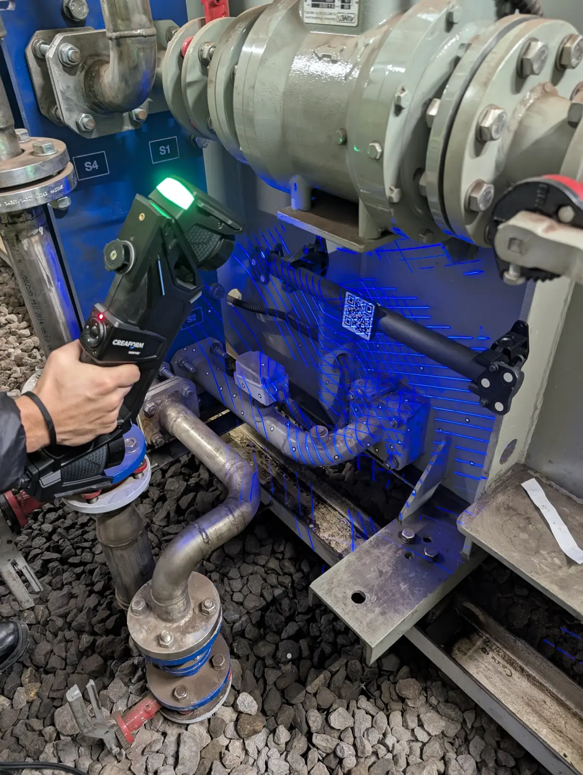
The HandyScan MAX is a metrology-grade portable laser scanner. It works by projecting blue laser crosses onto the surface of the object and capturing their reflection with calibrated cameras. The technician moves the scanner manually around the part, as if painting its surface with the laser, and the software reconstructs the geometry in real time on the laptop screen.
Its key specifications to understand what it can do:
- Measurement accuracy: +/-0.025 mm (25 microns). Sufficient for verifying machining tolerances, bearing fits and functional surfaces.
- Mesh resolution: 0.04 mm. Captures fine details such as engravings, surface textures and sharp edges.
- Working volume: From parts of a few centimetres to assemblies of 3-4 metres, without losing accuracy thanks to the optical target tracking system.
- Portability: Transported in a carrying case. Requires no assembly, tripod or special lighting conditions. Scanning can be performed directly on the factory floor, in the workshop or in the warehouse.
This is the equipment we use for 3D scanning of industrial parts: mechanical components, fixtures, moulds, housings, impellers, dies and any part that needs to be digitised with metrological precision.
Trimble X7: terrestrial scanner for facilities and buildings
The Trimble X7 is a terrestrial laser scanner (TLS). It works completely differently from the portable scanner: it is placed on a tripod, emits a laser beam that sweeps 360 degrees around it and captures millions of points of everything in its line of sight within minutes. It measures distances, angles and generates a dense point cloud of the entire environment.
- Range: From 0.6 to 80 metres. Covers everything from small rooms to large industrial warehouses.
- Angular accuracy: 1 arc second, with auto-compensation and auto-levelling. Equipment calibration is automatic at each station.
- Speed: Up to 500,000 points per second. A typical station (one scanner position) is completed in 2-8 minutes depending on the configured resolution.
- Automatic registration: Trimble Perspective software automatically registers (aligns) the different stations with each other, without the need for targets or manual intervention in most cases.
This is the equipment we use for 3D scanning of industrial facilities: warehouses, boiler rooms, process lines, piping routes, steel structures and any scenario where the complete spatial context needs to be captured.
The step-by-step process: from capture to deliverable
Understanding how industrial 3D scanning works means understanding that it is not a single step. It is a workflow with several phases, each with its own technical decisions. This is how we execute it on a real project:
Before turning on the scanner, we prepare the work. For parts, this involves placing adhesive targets (small 3 or 6 mm reflective markers) on the part or its surroundings. The scanner uses these targets as reference points to maintain accuracy throughout the entire sweep. If the part has highly reflective or transparent surfaces (polished steel, glass, translucent plastics), we apply a matte developer spray that is removed afterwards without leaving residue.
For facilities, preparation consists of planning the terrestrial scanner positions (stations) to ensure the entire area of interest is covered without blind spots. Access points, heights, obstacles and the presence of moving elements are studied. This advance planning makes the difference between an efficient scan and one that leaves gaps that require a return visit.
The technician performs the scan, capturing the geometry of the object or facility from different angles and positions to cover the entire surface of interest. With the portable scanner, this means moving the equipment around the part, ensuring the software records the entire surface without gaps. With the terrestrial scanner, successive stations are placed along the facility, with 30-40% overlap between positions to ensure good subsequent registration.
During capture, the software displays the point cloud being generated in real time. The technician verifies on site that no areas remain uncovered and that the data quality is adequate. If there are problematic areas (reflections, occlusions, difficult access), they are resolved on the spot with additional passes or position changes.
When scanning has been performed from multiple positions or stations, the different point clouds must be aligned with each other to form a single, coherent model. This process is called registration. In the case of the portable scanner, registration is automatic and in real time (the equipment self-positions using the targets). In the case of the terrestrial scanner, Trimble Perspective software performs automatic geometry-based registration and, if necessary, is manually adjusted to achieve the required accuracy.
The result of this phase is a unified point cloud: a set of millions of XYZ coordinates representing the complete surface of the scanned object or facility, referenced to a coherent coordinate system. If you want to delve deeper into what can be done with this point cloud, we recommend our article on how to go from a point cloud to a CAD model.
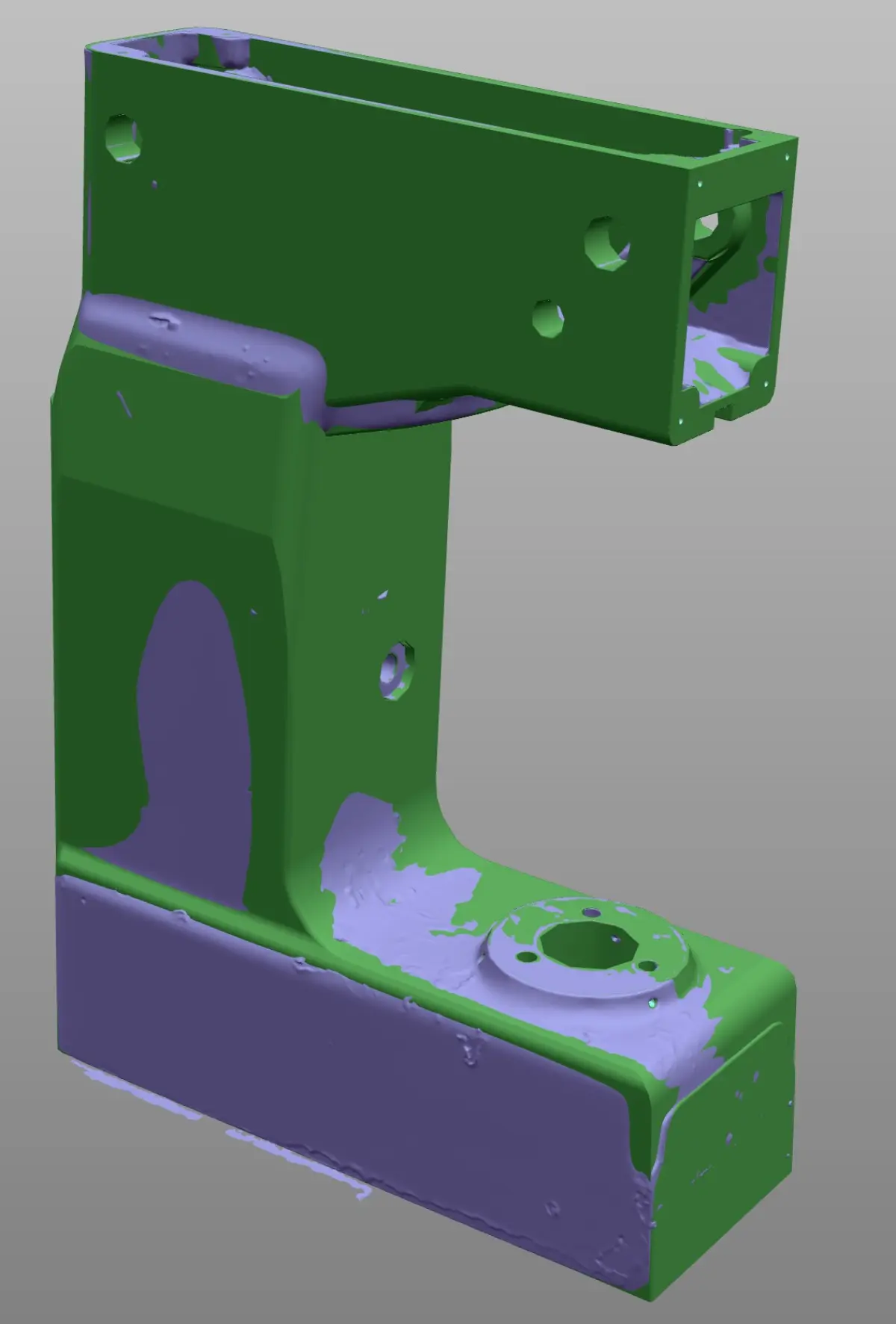
From the point cloud, a polygonal mesh (STL format) is generated. The mesh connects the points into triangles, forming a closed surface that faithfully represents the geometry of the object. It is a process that combines automatic algorithms with manual intervention by the technician: noise must be cleaned up, small gaps where the scanner could not access must be filled, and triangle density must be optimised according to the application (denser for areas of detail, lighter for flat surfaces).
The STL mesh is already a useful file in itself: it can be viewed, measured, sectioned and compared with other geometries. For applications such as 3D printing, the mesh may be the final deliverable. But for conventional mechanical manufacturing, the next step is CAD modelling.
When the project objective is to manufacture a part, modify a design or generate manufacturing drawings, the mesh is not enough: a parametric CAD model is needed. This step is known as Scan to CAD or reverse engineering, and it is where mechanical design knowledge makes the difference.
The technician builds a CAD model using the mesh as a reference, employing parametric modelling operations in Solid Edge: extrusions, revolutions, shells, patterns, fillets. It is not an automatic conversion: it is a manual process that requires interpreting the original design intent of the part, identifying functional surfaces, adjusting dimensions to standard values (bearing diameters, metric threads, gear modules) and defining appropriate tolerances.
Depending on the project scope, deliverables may include one or more of the following:
- Point cloud (E57, LAS, PLY formats): the raw scanning data, useful for as-built documentation, measurements and as a reference for future projects.
- Polygonal mesh (STL, OBJ): the triangulated surface, useful for visualisation, 3D printing and dimensional comparisons.
- Parametric CAD model (STEP, IGES, native Solid Edge format): the editable model, ready to manufacture, modify or integrate into an existing assembly.
- 2D dimensioned drawings (DWG, PDF): manufacturing documentation with dimensions, tolerances, surface finishes and material specifications.
- Deviation report: colour map comparing the scan mesh with the nominal CAD model, showing where and by how much the real part differs from the design.
Types of 3D scanning: laser vs. structured light
There are several 3D scanning technologies, but in the industrial field the two main ones are laser scanning and structured light scanning. Both capture surface geometry as point clouds, but they work differently and have distinct advantages.
Laser scanning (like the HandyScan MAX) projects lines or laser crosses and calculates the position of each point by triangulation. It is very robust in real industrial conditions: it works with variable ambient lighting, on dark surfaces or surfaces with pronounced curvature, and does not require controlled laboratory conditions.
Structured light scanning projects fringe patterns (white or blue light) onto the object and calculates the geometry from the deformation of those fringes. It offers very high capture speed and excellent resolution for small parts, but is more sensitive to ambient lighting and environmental conditions.
The choice between the two technologies depends on the type of part, the working environment and the precision requirements. If you want to understand in detail the differences, advantages and limitations of each, we analyse them in depth in our comparative article: structured light vs. laser 3D scanner.
Common industrial applications of 3D scanning
Industrial 3D scanning is not a solution in search of a problem. It is a tool that solves specific and recurring needs in industrial plants across all sectors. The most common applications we carry out at PROMECAD are:
- Reverse engineering and spare part manufacturing: Digitising parts without drawings to generate CAD models and manufacturing drawings. This is by far the most requested application. If you are interested in this specific case, we detail it in our guide on how to digitise a part without original drawings.
- Dimensional quality control: Comparing the manufactured part with the nominal CAD model to detect out-of-tolerance deviations. 3D scanning allows you to inspect the complete part, not just isolated points. We explain it in detail in our article on dimensional quality control with a 3D scanner.
- As-built facility documentation: Capturing the actual condition of a plant, a process line or an industrial building to have an updated digital twin that serves as a baseline for expansion, refurbishment or maintenance projects.
- Designing modifications on existing geometry: When you need to design a new component that must fit precisely onto an existing structure or piece of equipment, scanning gives you the exact geometric reference to work with.
- Assembly verification: Checking that a new piece of equipment, a structure or a piping system fits the actual available space before final installation, avoiding clashes and rework on site.
Frequently asked questions about industrial 3D scanning
How long does an industrial 3D scan take?
Scanning time depends on the size and complexity of the object. A medium-sized industrial part can be scanned in 15-45 minutes. A complete facility (warehouse, boiler room, process line) may require between half a day and two working days of fieldwork. Processing time in the office must be added: point cloud registration, mesh generation and, if required, CAD modelling. For a more detailed reference of timescales and costs, see our article on how much industrial 3D scanning costs.
Is it necessary to stop production to scan?
In most cases, no. 3D scanning is a non-contact, non-invasive process. We can scan facilities in operation as long as safe access to the areas of interest is guaranteed. Only in cases where there is excessive vibration, extreme surface temperatures or restricted access zones for safety reasons is it necessary to coordinate partial shutdowns. Our equipment is portable and self-contained: we do not need an electrical connection, compressed air or special infrastructure.
What is the difference between a point cloud, a mesh and a CAD model?
These are three levels of data processing from the scan. The point cloud is the raw capture: millions of XYZ coordinates representing the surface of the object, but without connection between them. The mesh (STL) connects those points into triangles, forming a closed surface that can be viewed and measured, but is not editable like an engineering model. The parametric CAD model is a file with intelligent geometry —extrusions, revolutions, dimensions, constraints— that can be modified, dimensioned, simulated and used for manufacturing. If you want to understand this transformation process better, we explain it in depth in our article on how to go from a point cloud to a CAD model.
What precision does industrial 3D scanning achieve?
It depends on the equipment used and the scale of the object. With the portable Creaform HandyScan MAX scanner, measurement accuracy is +/-0.025 mm (25 microns) and mesh resolution is 0.04 mm. This is the precision needed for mechanical parts with manufacturing tolerances. With the Trimble X7 terrestrial scanner, angular accuracy is 1 arc second with a useful range of 0.6 to 80 metres, which translates to millimetre-level precision for large-scale facilities. In both cases, precision is more than sufficient for common industrial applications: spare part manufacturing, quality control, as-built documentation and modification design.
Do you need to scan a part or a facility?
At PROMECAD we have over 20 years of experience in mechanical design and industrial engineering. Our team of specialists combines knowledge of 3D scanning equipment with the detail design experience needed to convert scanning data into truly useful deliverables: manufacturable CAD models, dimensioned drawings and complete technical documentation.
Based in Erandio (Bizkaia), we travel to the Basque Country, Cantabria, Navarra and throughout Spain with our portable equipment. We evaluate each project individually and provide you with a technical approach and a fixed quote before we start.
Request a no-obligation quote or call us directly at 946 49 00 27. We will respond within 24 hours with an initial assessment of your project.