September 4, 2025
Dimensional quality control with 3D scanner: complete guide for manufacturers
You produce a series of machined parts, receive a batch of castings from your supplier, or have just adjusted an injection mould. The key question is always the same: does the actual part match the design? Dimensional quality control with a 3D scanner gives you the answer quickly, visually and comprehensively: you scan the manufactured part, compare it with the nominal CAD model and obtain a colour deviation map that shows, point by point, where the part passes and where it does not. In this guide we explain how the entire process works, when it makes sense compared to traditional methods, and what type of reports you can obtain.
What is dimensional quality control and why it matters
Dimensional quality control consists of verifying that the dimensions, shapes and tolerances of a manufactured part correspond to the design specifications. It is the barrier between a part that works and a part that creates assembly problems, causes end-customer rejections or compromises equipment safety.
In any manufacturing process —machining, casting, stamping, plastic injection, welding— there are deviations from the nominal design. The question is not whether there are deviations, but whether those deviations fall within the admissible tolerances. A shaft that should measure 50.00 mm and measures 50.03 mm may be perfectly acceptable if the tolerance is h7, but unacceptable if the tolerance is h6. Dimensional control is what allows you to make that decision with objective data, not subjective judgement.
Traditionally, this control has been performed with manual tools (callipers, micrometres, gauges) or with coordinate measuring machines (CMM). These methods remain valid for many applications, but have significant limitations when the part has complex geometries, curved surfaces, or when you need to inspect the entire surface rather than just a few points. That is where dimensional quality control with a 3D scanner comes in.
Traditional methods vs 3D scanner
Before delving into the 3D scanner workflow, it is worth understanding what each inspection method offers and how they differ. This comparison will help you decide which makes the most sense for your specific case. If you want an in-depth comparison between 3D scanner and coordinate measuring machine, we have prepared a dedicated article on 3D scanner vs CMM.
| Criterion | Calliper / Gauges | CMM | 3D Scanner |
|---|---|---|---|
| Points measured | 1 per measurement | Tens to hundreds | Millions |
| Typical accuracy | +/-0.01 mm | +/-0.002-0.005 mm | +/-0.15 mm (HandyScan MAX) |
| Time per part | 5-30 min | 15-60 min | 5-15 min (scanning) |
| Portability | Full | None (fixed equipment) | Full (portable) |
| Complex surfaces | Very limited | Limited | Excellent |
| Global visualisation | No | Partial | Complete colour map |
| Training required | Basic | High (programming) | Medium |
Callipers and gauges are essential tools for quick point measurements in the workshop. The CMM is the reference when you need maximum precision at specific points and very tight tolerances (below 0.01 mm). The 3D scanner excels when you need to compare a manufactured part with a 3D CAD model globally: you do not measure isolated points, you capture the entire surface and see at a glance where the problems are.
In practice, all three technologies coexist in many factories. The question is not which is better in the abstract, but which best suits each type of part, tolerance and inspection volume. You can explore this decision further in our article on how much industrial 3D scanning costs, where we also address comparative costs.
How dimensional inspection with a 3D scanner works
The workflow for performing dimensional quality control with a 3D scanner follows four well-defined phases. Each requires specific software and technical judgement.
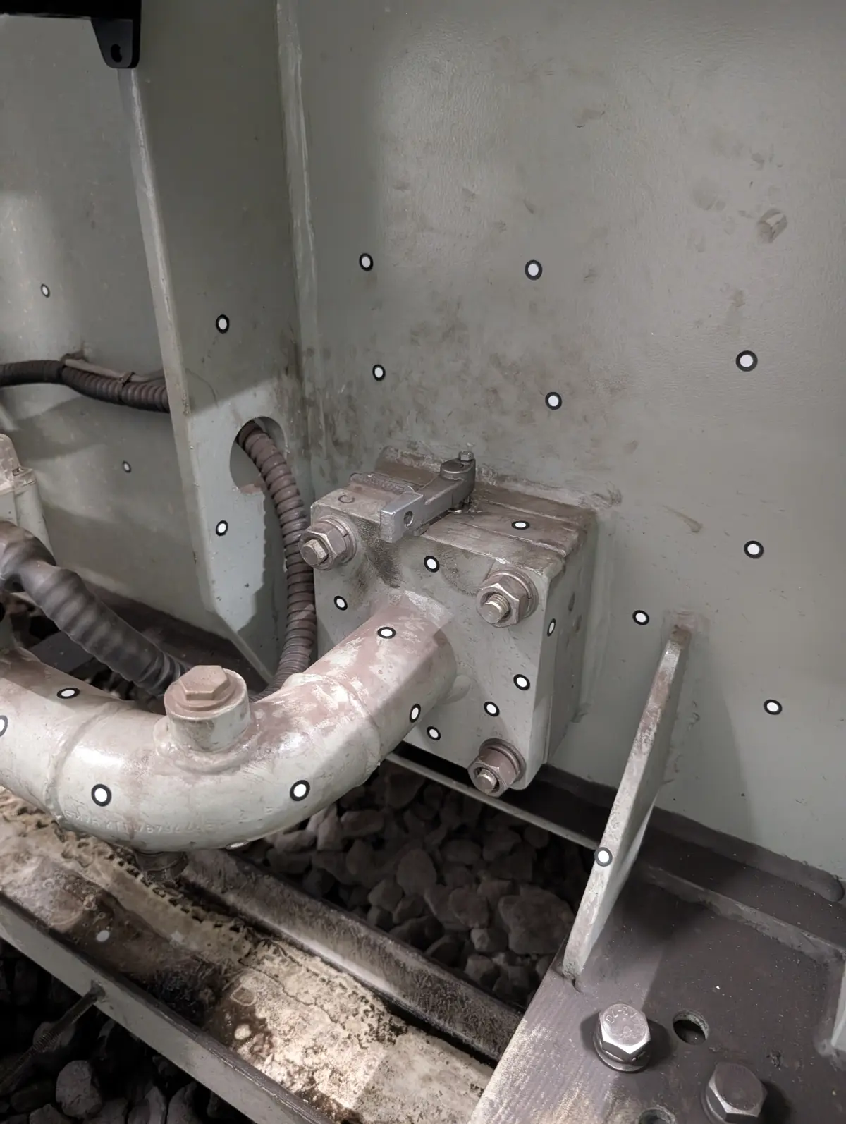
Scanning the manufactured part
The first step is to capture the actual geometry of the part using a 3D scanner. At PROMECAD we use the Creaform HandyScan MAX, with an accuracy of +/-0.15 mm and a resolution of 0.04 mm, which allows us to capture millions of surface points in a matter of minutes. Scanning can be performed at our facilities or directly at the client's plant: the equipment is fully portable and does not require special environmental conditions. For very large parts or complete facilities, we complement with our Trimble X7, which covers ranges from 0.6 to 80 metres.
The scanning result is a dense point cloud representing the actual surface of the part as it has been manufactured, without interpretations or approximations. This is the raw material for dimensional analysis.
Alignment with the nominal CAD model
Once the point cloud (or the processed polygonal mesh) is obtained, the next step is to align it with the reference CAD model —the nominal design against which the inspection will be performed—. This alignment is critical because it conditions all subsequent results. It can be done in several ways: best-fit (least squares adjustment), datum alignment (functional references of the part) or RPS alignment (Reference Point System) according to the drawing specifications.
The choice of alignment method is not trivial. A best-fit alignment distributes deviations uniformly and is useful for a general overview, but can mask functional problems. A datum alignment reflects how the part will actually be assembled and therefore shows the deviations that really matter. At PROMECAD, we always agree the alignment method with the client before generating the report.
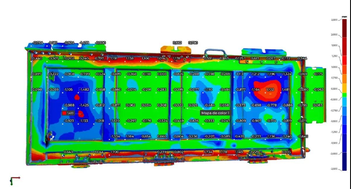
Generating the deviation map (colour map)
This is the most visual and intuitive part of the process. The software compares each point on the scanned surface with the nominal CAD surface and calculates the deviation in millimetres. These values are represented as a colour map over the part geometry: typically, green indicates zones within tolerance, blue indicates the part has less material than nominal (negative deviation) and red indicates excess material (positive deviation).
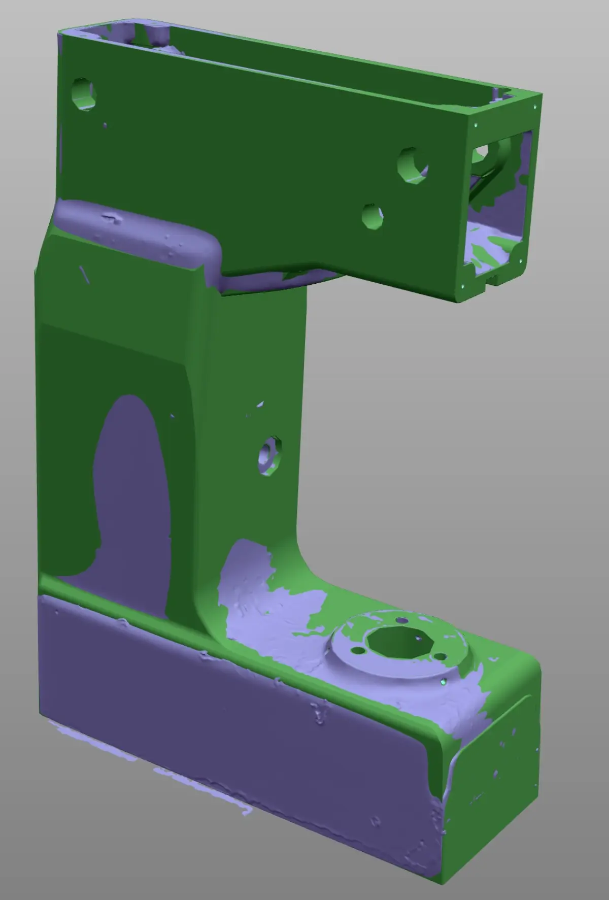
The CAD vs actual part comparison with colour map is an extraordinarily effective communication tool. A quality manager, a buyer or even a supplier who is not a metrology specialist can understand at a glance where the problem is and its magnitude. It is much more eloquent than a table of numbers and allows quick decisions on acceptance, rejection or rework.
Dimensional report with GD&T tolerances
The colour map provides a global view, but to formally document the inspection a GD&T dimensional report with 3D scanner is needed that includes the specific drawing dimensions with their tolerances, the measured value and the result (OK/NOK). The typical GD&T characteristics that can be verified with 3D scanning include:
- Linear and diametrical dimensions: distances between planes, hole and shaft diameters.
- Flatness: deviation of a surface from an ideal plane.
- Cylindricity and circularity: actual shape of cylindrical and circular surfaces.
- Perpendicularity and parallelism: angular relationship between surfaces or axes.
- Surface profile: overall deviation of a complex surface from the CAD.
- Position: actual location of holes, slots or features relative to datums.
The final report combines the global colour map with individual dimension tables, cross-sections where necessary, and conformity conclusions. It is a document that serves both for internal decision-making and for communication with suppliers or clients.
Specific manufacturing applications
First article inspection (FAI)
First article inspection FAI with 3D scanning is one of the most demanded applications, especially in sectors with strict FAI requirements such as industrial aerospace. When a supplier delivers the first parts of a new series —a first machining article, a first plastic injection, a first casting— you need to validate that the part complies before approving series production. With 3D scanning you can verify the entire part geometry in a single session, generating a complete FAI report with all drawing dimensions.
The advantage over manual point-by-point inspection is twofold: on one hand, you capture the entire surface (allowing you to detect problems in areas you would not have measured); on the other, the process is much faster, reducing approval time and consequently time-to-market.
Series and sampling control
Once production is approved, periodic dimensional control allows process drifts to be detected before they generate rejections. With the 3D scanner you can inspect parts by sampling (for example, one out of every 50) and maintain a historical record of deviations. If you observe that a dimension is gradually increasing from batch to batch, you can intervene in the process before the part goes out of tolerance. This is especially valuable in processes such as plastic injection, where mould wear causes gradual changes in part dimensions. In sectors with hygiene requirements such as the food industry, this periodic control is key to ensuring that tanks, moulds and production lines maintain their dimensional specifications.
Non-contact measurement of fragile or flexible parts
There are parts that cannot be measured with contact methods without deforming or damaging them: thin sheets, rubber or silicone parts, electronic components, composite parts or even ceramic parts. Non-contact measurement of fragile or flexible parts with a 3D scanner solves this problem: capture is entirely optical, with no physical contact with the part. The scanner projects light (laser or structured light) and collects the reflection with its cameras. The part experiences no pressure or deformation during measurement.
Deformation and wear analysis
Another common application is scanning a part after a period of service to analyse how it has deformed or worn. By comparing the scan of the used part with the original CAD model (or with a previous scan of the new part), it is possible to quantify exactly where and how much material has been lost or how the geometry has changed. This is especially useful for forming tools, dies, moulds and components subjected to fatigue or abrasion. In the automotive sector, this type of analysis is common for validating prototypes and short runs.
Case study: batch rejection with objective data
Dimensional dispute with casting supplier
Sector: Industrial machinery — Part: Gearbox housing in GG25 grey cast iron, dimensions 420 x 280 x 310 mm.
Problem: A gearbox manufacturer received a batch of 24 cast housings from a new supplier. When attempting to install the bearings and shafts, the technicians detected that the bores did not fit correctly in several units. The casting supplier claimed that the parts were compliant, based on point measurements with a calliper.
Solution: PROMECAD scanned 6 housings from the batch (25% sampling) with the HandyScan MAX and compared them with the CAD model provided by the client. The deviation maps revealed that, while the bore diameters were correct, the coaxiality between the input shaft and output shaft bores was out of tolerance in 4 of the 6 scanned parts (0.35 mm deviation against a 0.15 mm tolerance). This error was undetectable by measuring individual diameters with a calliper.
Result: With the dimensional report as objective evidence, the client negotiated with the supplier for the entire batch to be recast at no cost. The colour map was decisive because it made visible a problem that point measurements could not capture. The supplier corrected their casting tooling based on the report data.
This type of situation is more common than it seems. In our experience performing 3D part scanning, we have seen many cases where the value of scanning lies not just in detecting the problem, but in documenting it in a way that all parties understand and can resolve without ambiguity. If you want to learn about other situations where 3D scanning makes a difference on the factory floor, we recommend our article on the 5 situations where your factory needs 3D scanning.
When to choose 3D scanner and when CMM
A question we are frequently asked is whether the 3D scanner can replace the CMM. The honest answer is that it depends on the case. There are clear situations for each technology:
Choose 3D scanner when:
- The part has free-form surfaces or complex geometries (turbines, blades, organic housings).
- You need a global view of the entire surface, not just specific points.
- The part is fragile, flexible or cannot be clamped on a CMM table.
- You need portability: measuring the part on site, in the plant, in the workshop.
- The volume of parts to inspect is high and you need to reduce times.
- The required tolerance is above +/-0.1 mm.
Choose CMM when:
- Tolerances are very tight (below +/-0.01 mm).
- You need to measure internal features that the scanner cannot see (deep holes, internal slots).
- Your sector's regulations specifically require contact measurement or CMM certification.
- The part is prismatic and the dimensions are essentially distances between planes and diameters.
In many cases, the best strategy is to combine both technologies: the 3D scanner for a quick global verification and the CMM for the most critical dimensions. We have developed a detailed comparison in our article on 3D scanner vs CMM: when to use each technology.
Frequently asked questions
What precision does quality control with a 3D scanner achieve?
It depends on the scanner used. With equipment such as the Creaform HandyScan MAX, accuracy reaches +/-0.15 mm with a resolution of 0.04 mm, sufficient for the majority of industrial quality control applications. For tolerances below 0.01 mm, a CMM remains more suitable.
Can quality control be performed with a 3D scanner without a reference CAD model?
Yes, although with limitations. Without a nominal CAD model, you can compare parts against each other (for example, a good part against a suspect one), measure absolute dimensions or verify symmetries. However, the complete workflow with deviation maps and GD&T tolerances requires a reference CAD model.
How long does a dimensional inspection with a 3D scanner take?
Scanning a medium-sized part (up to 500 mm) takes 5 to 15 minutes. Generating the report with deviation maps and GD&T analysis can take between 30 minutes and 2 hours, depending on complexity and the number of dimensions to verify. In total, a complete report can be delivered on the same day.
Does the 3D scanner replace the coordinate measuring machine (CMM)?
It does not replace it, but rather complements it. The 3D scanner is superior in speed, portability and the ability to capture complex surfaces. The CMM is more precise for individual points and very tight tolerances. Many factories use both technologies depending on the type of part and the tolerance required.
Request a quality control study for your part
If you need to verify the dimensional conformity of your parts, resolve a dispute with a supplier or establish a quality control protocol with a 3D scanner, we can help. At PROMECAD we have over 20 years of experience in industrial mechanical design and have state-of-the-art 3D scanning equipment to provide you with complete dimensional reports, with deviation maps, GD&T analysis and technical recommendations.
We operate from Erandio (Bizkaia) and travel to your plant in the Basque Country, Cantabria, Navarra or wherever you need us throughout Spain. Tell us about your case and we will send you a proposal within 24 hours.
Contact us or call us directly at +34 94 406 42 83.