November 5, 2025
5 situations where your factory needs 3D scanning (and probably doesn't know it)
In the day-to-day operations of an industrial plant, there are problems that are assumed to be unavoidable: parts that cannot be replicated, drawings that no longer reflect reality, discrepancies with suppliers that are resolved by guesswork. But most of these situations share a common solution that many companies still overlook. We explain how industrial 3D scanning works and why it could be exactly what your factory needs.
1. We have a critical part that has broken and the supplier no longer exists
"The coupling on the gearbox of line 3 has failed. It was manufactured by a German company that closed ten years ago and we don't have any drawings."
This is probably the most common situation we encounter on the factory floor. Machinery that has been running for decades, components that were custom-made and suppliers that have simply disappeared. When you need to replicate a part without manufacturing drawings, the classic alternative is to take manual measurements with callipers and micrometres, make a sketch and hope the workshop correctly interprets the dimensions. The result, in the best case, is a part that "more or less" fits.
With 3D part scanning, the process is radically different. A portable laser scanner captures millions of points on the surface of the original part, generating a point cloud with sub-millimetre precision (+/-0.15 mm with our Creaform HandyScan MAX). From there, a solid CAD model is built that any CNC workshop can machine directly. If you want to learn the details about the equipment, phases and deliverables of this process, we recommend our step-by-step guide on how industrial 3D scanning works.
This process is what is known as reverse engineering with a 3D scanner: starting from a physical object to obtain its complete digital model, with all its geometries, radii, chamfers and tolerances. No information is lost in transcription and the result is a faithful replica, not an approximation.
Furthermore, once you have the CAD model, you keep it forever. If the part fails again in five years, manufacturing is immediate. It is an investment that eliminates a recurring risk and definitively solves the problem of 3D scanning spare parts for old machinery. If you are in this situation, we recommend our comprehensive guide on how to digitise a part without original drawings, where we explain the process step by step with a real case study.
2. We have made modifications to the plant and the drawings no longer match reality
"We want to expand the packaging area, but the as-built drawings are from 2008. Since then we have moved piping, added a compressor and replaced the entire base frame of line 2."
Industrial plants are living organisms. Every year equipment is added, piping routes are modified, electrical panels are relocated. After a few years, the original drawings become historical documents that bear little resemblance to what is actually installed. And when the time comes to digitise an existing industrial facility for a refurbishment, the problem becomes apparent: the engineering project starts from a false baseline.
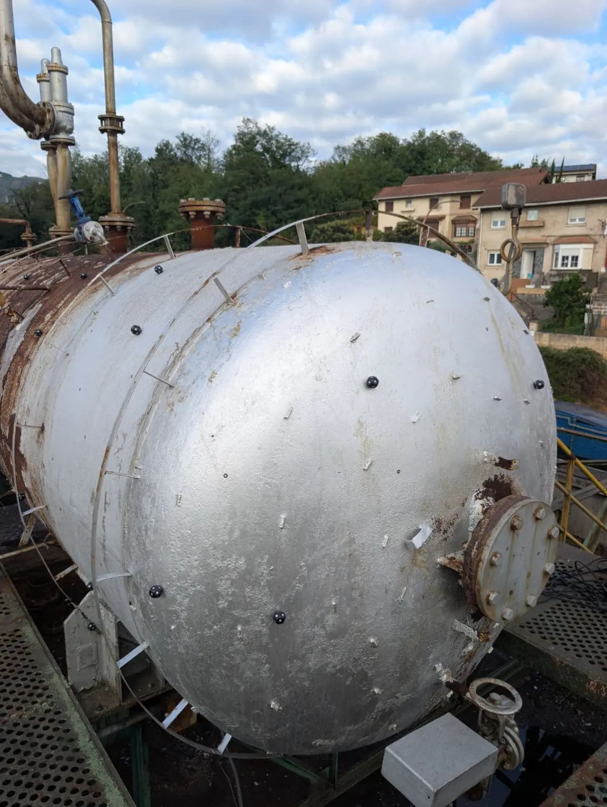
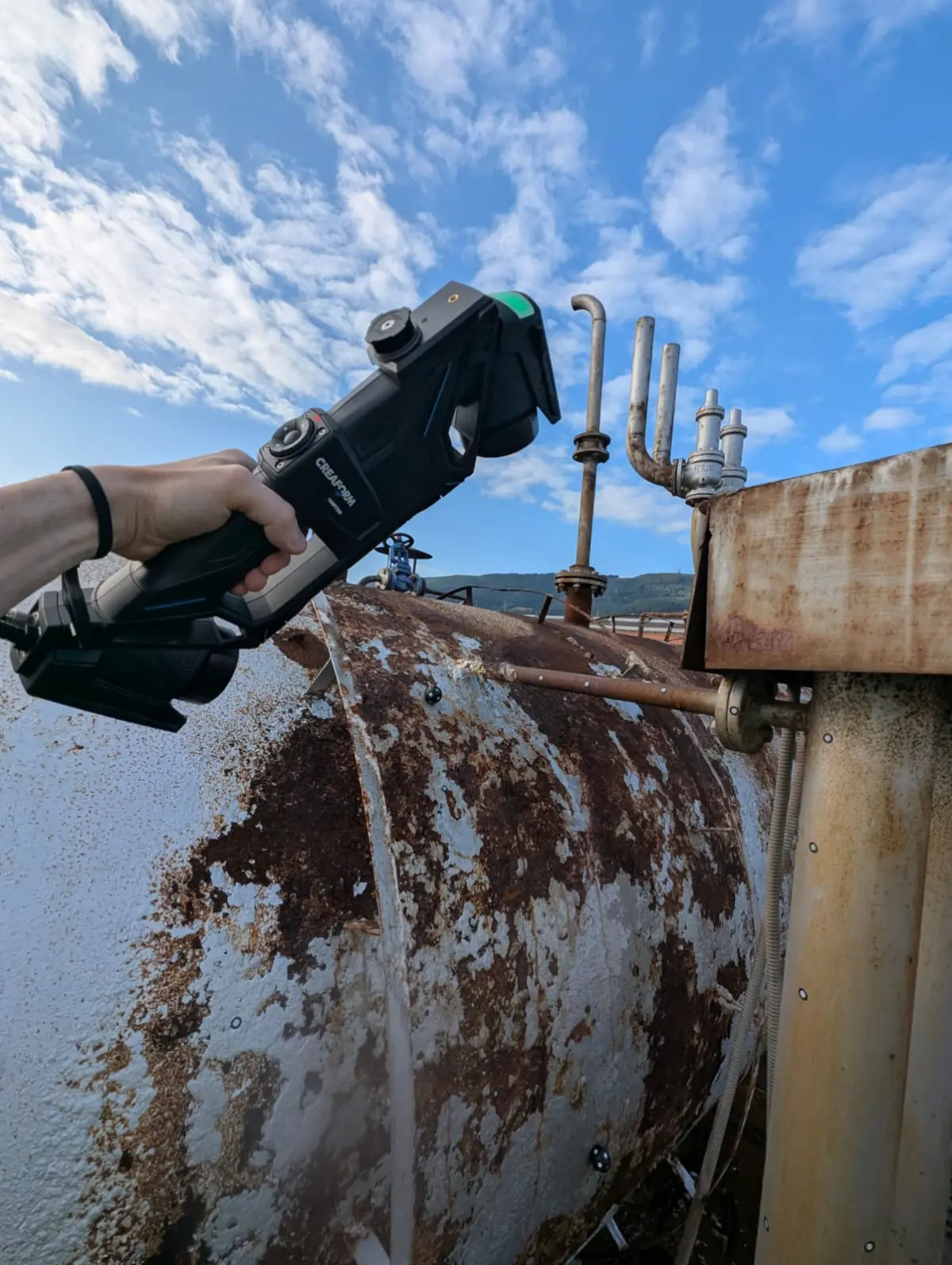
3D facility scanning resolves this comprehensively. Using a terrestrial laser scanner (TLS), the entire plant is captured as it stands today: structure, equipment, piping, cable trays, ventilation ducts, everything. The result is a high-density three-dimensional point cloud that serves as a reliable baseline for any refurbishment, expansion or new equipment integration project.
The advantage is not just precision. It is speed. A laser scan of facilities covering a 2,000 square metre warehouse can be completed in one or two days without interrupting production. The data is processed and delivered in formats compatible with any engineering software: Revit, AutoCAD Plant 3D, Solid Edge.
We have seen refurbishment projects where engineers discover clashes during the design phase precisely because they were working on a model updated by scanning, rather than trusting obsolete drawings. Those clashes detected on screen would have been real collisions on site, with the cost and delays that entails. If you want to learn the details of how this process works, we recommend our guide on Scan to BIM for digitising industrial plants.
3. We reject parts from the supplier but cannot demonstrate the deviation with data
"We receive batches of cast housings that don't fit during assembly. The supplier says they are within tolerance, we say they are not, and in the end it's our word against theirs."
Dimensional control is one of the most powerful and least known applications of 3D scanning in manufacturing environments. When you need to compare a manufactured part with its 3D CAD model, a scanner allows you to perform a complete point-to-point deviation analysis, generating a colour map that visually and unequivocally shows where the actual part departs from the nominal and by how much.
The resulting report leaves no room for interpretation. Each zone of the part is coloured according to its deviation: green within tolerance, yellow at the limit, red out of specification. With numerical values at each control point. It is objective technical evidence that you can share with your supplier, and that any quality engineer understands instantly.
Unlike traditional inspection methods with a CMM (coordinate measuring machine), which measure discrete points, 3D part scanning captures the entire surface. This means you not only detect deviations where you expected to find them, but also deformations or defects in areas that a point-based inspection would have missed.
For companies that manage supplier quality, this ability to document deviations comprehensively and repeatably changes negotiation dynamics. It is no longer about perceptions, but about data. The process for comparing a manufactured part with a 3D CAD model is fast, objective and generates traceable documentation that you can archive for future audits. We explain the entire workflow in our guide on dimensional quality control with a 3D scanner, including sectors with particularly strict requirements such as automotive.
4. We need to adapt a fixture but don't have the original CAD
"We have a welding fixture that was designed fifteen years ago for an old part number. Now we need to adapt it to the new part, but the CAD was lost when we changed our IT system."
The digitisation of production fixtures and tooling is a need that frequently arises in plants in the automotive, aerospace and general metalworking sectors. Welding fixtures, verification jigs, machining cradles... these are custom-made elements that have undergone modifications over time and whose original documentation, in many cases, simply does not exist.
Using our 3D scanning services, we capture the complete geometry of the fixture as it stands today, including all modifications made over the years. From the 3D model obtained, you can work on a real baseline to design the adaptation, rather than starting from scratch or resorting to trial and error in the workshop.
The savings are twofold. On the one hand, design time is drastically reduced because there is no need to build the complete fixture model from manual measurements. On the other hand, fitting errors in the workshop are minimised because the digital model faithfully reflects the physical reality, including imperfections and deformations accumulated through use.
In our experience, digitising a complex fixture that would manually take two weeks of measurement and modelling is completed in two or three days with 3D scanning, including delivery of the parametric CAD model ready to be modified. It is a clear example of reverse engineering with a 3D scanner applied to the continuous improvement of production processes.
5. We want to optimise an existing design but only have the physical part
"We have been manufacturing this bracket with the same design for years. We know it's over-engineered, but to redesign it we would need the CAD and all we have is the physical part."
Optimising existing components is one of the most direct ways to reduce manufacturing costs, assembly weight and assembly times. But to optimise, you first need a digital model to work with. And when the only starting point is the physical part, part digitisation through 3D scanning is the essential first step.
The industrial 3D scanning process generates a model that not only reflects the current geometry of the part but also allows it to be analysed with simulation tools (FEA, CFD) to identify where there is excess material, where stresses are concentrated and which geometric modifications would improve performance. The path the information travels from capture to the manufacturing file is what is known as the Scan to CAD process.
A common example: metal brackets and supports designed in an era when calculations were conservative and material was cheap. Today, with topology optimisation tools and additive manufacturing, many of these components can be redesigned with a 30 to 50 percent weight reduction without compromising their strength. But it all starts with having the digital model, and that is where scanning comes in.
Additionally, scanning allows you to document the current design before introducing changes. If the new version presents any problems in service, you can always manufacture the original part again from the stored model. It is a safety net that did not exist when you only had the part sitting on the warehouse shelf.
Do any of these situations sound familiar?
If you have recognised your factory in any of these five scenarios, you are not alone. These are situations we encounter practically every week in industrial companies of all sizes and sectors. What they all have in common is that they are resolved with the same core technology: a professional 3D scanner, appropriate processing software and, above all, professionals with experience in industrial environments who know how to interpret the data and convert it into real solutions.
At PROMECAD we have over twenty years of experience in industrial mechanical design, and we work with state-of-the-art 3D scanning equipment. We understand the problems because we have experienced them alongside our clients, and we know that each case requires a specific approach. Scanning a 50-millimetre part with sub-millimetre precision is not the same as surveying a 10,000 square metre petrochemical plant.
If you want to get an idea of the investment involved before contacting us, we recommend consulting our guide on how much an industrial 3D scanning service costs. And if you want to know how 3D scanning can be applied to your specific case, tell us about your situation. We analyse each project on an individual basis and propose the most efficient solution, with no obligation. Sometimes the answer is simpler and faster than you imagine.