August 14, 2025
From point cloud to CAD model: the complete Scan to CAD process
You scanned a part in 3D. Now you have millions of points on a screen. And the inevitable question: now what? The reality is that a point cloud is not a CAD model, it is not a drawing and it cannot be sent for manufacturing directly. Between the scan and a useful file for machining, simulation or documentation, there is a technical process that makes the difference between raw data and a professional deliverable. In this guide we explain each phase of that journey —from the point cloud to the polygonal mesh and from the mesh to the parametric CAD model— with the technical decisions made at each step.
What a point cloud is (and what it is NOT)
A 3D point cloud is exactly what its name implies: a massive set of points in space, each defined by its X, Y, Z coordinates. When a 3D scanner captures the surface of a part or facility, the result is millions of these points that, viewed together, reproduce the shape of the scanned object.
What a point cloud is NOT:
- It is not a continuous surface. It is a collection of discrete points. Between one point and the next there is a void. It does not define faces, edges or volumes.
- It is not a CAD model. It has no design operations (extrusions, pockets, fillets), no dimensions, no tolerances. It cannot be edited like a Solid Edge or AutoCAD file.
- It cannot be manufactured directly. A CNC machining center needs defined geometry (NURBS surfaces or solids), not a dispersion of points.
- It has no design intent. A 20.03 mm hole in the point cloud may represent a nominal 20 mm hole with H7 tolerance. The cloud does not know that; it only reflects what the scanner measured.
Understanding this distinction is fundamental. Many companies hiring a 3D part scanning service for the first time expect to receive a CAD model ready for manufacturing directly from the scanner. The scan is the essential first step, but the real value lies in what happens next: the Scan to CAD process.
From point cloud to polygonal mesh (STL)
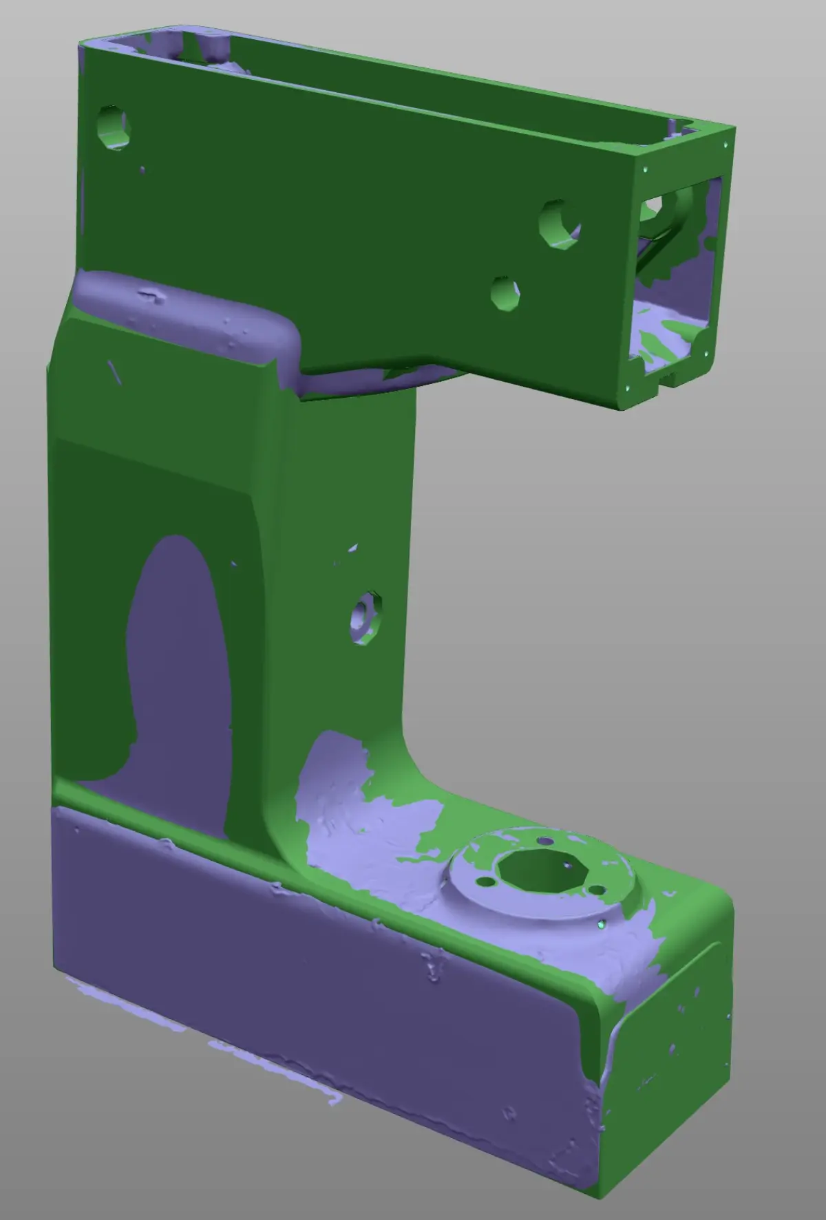
The first processing applied to the raw point cloud is converting it into a polygonal mesh: a surface formed by triangles (or, less frequently, quadrilaterals) that approximate the continuous geometry of the object. The most common formats are STL and OBJ. This intermediate step is essential because a mesh does define a closed surface, unlike the loose point cloud.
Noise cleaning and filtering
Every point cloud has noise: erroneous points caused by reflections, dust particles, scanner vibrations or hard-to-access areas. The first step is to eliminate these outlier points and smooth areas where point density is irregular. This filtering is done with specialized software and requires technical judgment: overly aggressive filtering removes real details; too-light filtering leaves artifacts that contaminate subsequent phases.
Gap closure and optimization
It is practically impossible to scan 100% of a part's surface in a single session. There are always hidden areas (hole bottoms, resting faces, internal cavities) that create gaps in the mesh. The technician closes these gaps by interpolating the surrounding geometry, respecting surface continuity. In mechanical parts, many of these gaps coincide with known geometries (cylinders, planes, threads) that can be reconstructed with certainty.
Mesh optimization also includes reducing the number of triangles in flat areas (where they add no information) and keeping them dense in curved or detailed areas. A well-optimized mesh is computationally manageable without losing geometric fidelity.
When the mesh is sufficient and when it is not
There are applications where the STL mesh is the valid final deliverable:
- 3D printing / additive manufacturing: 3D printers work directly with STL files.
- Visualization and documentation: to create renders, videos or visual documentation of a part's condition.
- Dimensional inspection by comparison: comparing the scan mesh with the theoretical CAD model to detect deviations in a dimensional quality control.
- Archiving the actual state: documenting how a part or facility looks at a given point in time.
But if you need to manufacture the part by CNC machining, modify the design, generate dimensioned 2D drawings or integrate the part into a CAD assembly, the mesh is not sufficient. You need a parametric CAD model. That is where the most critical phase of the process begins.
From mesh to parametric CAD model
This is the phase that requires the most technical knowledge and judgment. Going from a mesh —which is an approximate representation of reality— to a parametric CAD model —which is an idealized representation with design intent— is not an automatic conversion. It is a work of technical interpretation that can only be done by a professional with experience in mechanical design.
NURBS surfaces vs parametric solid
There are two main approaches to building the CAD model from the mesh:
- NURBS surface modeling: mathematical surfaces (NURBS) are fitted directly onto the mesh. This approach is ideal for organic or free-form geometries: turbine blades, aerodynamic housings, mold surfaces, castings with complex shapes. The result is a high-quality surface model, but not necessarily parametric (it does not have an editable feature tree).
- Parametric solid modeling: the model is built from scratch using classic design operations (2D sketches, extrusions, revolutions, pockets, fillets, patterns), using the mesh as a dimensional reference. The result is a native model with a complete feature tree, fully editable. This approach is ideal for mechanical parts: shafts, flanges, housings, brackets, tooling.
In practice, many projects combine both approaches: NURBS surfaces for free-form areas and solid modeling for regular geometric areas.
Interpreting the design intent
This is the point where the technician's experience makes the biggest difference. A scanner captures the real geometry of the part, including wear, deformations, manufacturing imperfections and assembly tolerances. A hole that measures 20.07 mm in the scan was probably designed as a 20 mm hole. A plane that shows a slight curvature of 0.05 mm was conceived as a perfect plane.
The technician building the CAD model must interpret these measurements and decide: do I model the part as it is (as-built) or as it should be (as-designed)? The answer depends on the end use. If the goal is to manufacture a new replacement, the correct approach is to model the nominal geometry, compensating for wear. If the goal is to document the current state for an inspection, it is modeled as-is. This decision is made in dialogue with the client and documented in the verification report.
Geometric constraints and regularization
Regularization is the process of applying geometric constraints that make mechanical sense: symmetries where they exist, parallelisms, perpendicularities, concentricities, rounded nominal dimensions. A scanned part may show that two holes are at 100.12 mm and 99.87 mm from a reference plane. If the original design intended both at 100 mm, the technician regularizes that dimension to 100 mm in the CAD model.
Regularization is not losing precision: it is recovering the design intent that the original manufacturing process and subsequent wear have blurred. It is what turns a scan into a useful model for reverse engineering.
Difference between STL mesh and solid CAD model
| Feature | STL/OBJ Mesh | Parametric CAD Model |
|---|---|---|
| Definition | Set of triangles approximating the surface | Exact mathematical geometry with design operations |
| Editable | Only mesh deformation (limited) | Fully editable (change dimensions, add operations) |
| Dimensions and tolerances | Does not contain them | All dimensions can be dimensioned and toleranced |
| 2D drawings | Cannot be generated | Automatically generated from the model |
| CNC machining | Not usable (except in very specific CAM software) | Directly programmable in any CAM system |
| 3D printing | Native working format | Exported to STL for printing |
| FEA simulation | Possible but with limitations | Fully compatible with any FEA software |
| File size | Can be very large (millions of triangles) | Lightweight (mathematically defined geometry) |
The practical conclusion: if you need to manufacture, modify, document with drawings or integrate into an assembly, you need the CAD model. If you need to 3D print or simply visualize, the mesh may be sufficient.
Software used in the process
The Scan to CAD workflow involves different types of software for reverse engineering and 3D scanning, each specialized in a phase:
- Point cloud capture and processing software: Geomagic Wrap, Geomagic Design X, PolyWorks. These programs handle cleaning the cloud, generating the mesh, closing gaps and, in the case of Design X, facilitating the transition to CAD modeling with automatic primitive and surface fitting tools.
- CAD modeling software: at PROMECAD we work with Solid Edge and AutoCAD for building the final parametric model, 2D drawings and technical documentation. Solid Edge is especially powerful for 3D mechanical parts due to its synchronous modeling and its integration with scan data. AutoCAD is used for 2D drawings and DWG/DXF documentation.
- Dimensional verification software: Geomagic Control X, PolyWorks Inspector. These are used to compare the generated CAD model with the original mesh and produce the deviation map that accompanies the deliverable.
It is important to understand that no software automatically converts a point cloud into a quality parametric CAD model. There are auto-surfacing and primitive recognition functions, but the result always needs review, correction and interpretation by a specialized technician. The software is the tool; the technical judgment of a team experienced in industrial 3D scanning is what defines the quality of the result.
Common delivery formats
The delivery formats for industrial 3D scanning depend on the use the client will give the file. These are the most common:
- STEP (.stp, .step): the universal CAD exchange format. Compatible with virtually any mechanical design, simulation or manufacturing software. It is the most requested.
- IGES (.igs, .iges): older standard format, still used in some industrial environments. Supports surfaces and solids.
- Parasolid (.x_t, .x_b): native format of the kernel used by Solid Edge and other CAD programs. Excellent geometric quality.
- DWG / DXF: AutoCAD formats for 2D drawings, laser cutting, engraving and technical documentation.
- STL (.stl): triangle mesh for 3D printing, visualization and as a reference of the original scan.
- OBJ (.obj): similar to STL but with color and texture support. Used for visualization and heritage.
- Native: if the client works with Solid Edge or AutoCAD, we can deliver in the native format of their software with a complete feature tree.
In each PROMECAD project, delivery formats are defined in the initial phase together with the client. If you are not sure which format you need, contact us and we will advise you based on your workflow.
Practical case: from scan to CNC machining file
Valve body for a food production line
Situation: A food sector company needed to manufacture 4 replicas of an AISI 316L stainless steel valve body. The original part had been in service for over 15 years, with visible wear on the seating areas. No drawings or CAD model existed. The original valve manufacturer no longer supplied that model.
Phase 1 — Scanning: We scanned the part with our Creaform HandyScan MAX (accuracy ±0.15 mm, resolution 0.04 mm). The complete capture, including accessible internal cavities, generated a cloud of 3.2 million points. Scanning time: approximately 25 minutes.
Phase 2 — Mesh: We processed the point cloud in Geomagic, eliminating noise and closing gaps corresponding to the resting areas. We generated an optimized STL mesh of 1.4 million triangles.
Phase 3 — CAD model: We built the parametric solid model in Solid Edge, regularizing dimensions to nominal values (the seating diameters measured between 25.08 and 25.14 mm — they were modeled at 25 mm H7). The free-form areas of the body were modeled with NURBS surfaces fitted to the mesh. Modeling time: approximately 12 hours of technical work.
Phase 4 — Verification: We compared the CAD model with the scan mesh. Maximum deviations were found in the areas where we compensated for wear (up to 0.12 mm). The rest of the model fitted within ±0.05 mm. We documented each deviation and its justification.
Delivery: STEP model for CAM programming, 2D drawings in DWG with dimensions, tolerances and surface finishes, STL reference mesh and dimensional verification report. The client's workshop machined all 4 parts directly from our files without the need for additional adjustments.
If you want to learn more details about how a complete reverse engineering project works, or if you have a part that needs digitizing, you can also check our guide on how to digitize a part without original drawings.
Frequently asked questions
What is a 3D point cloud and how is it used?
A point cloud is a set of millions of XYZ coordinates representing the surface of a scanned object or space. It is not a solid model or a continuous surface: it is a discrete representation of points in space. It is used as a basis for generating polygonal meshes, parametric CAD models, 2D drawings or BIM models, depending on the project needs.
What is the difference between an STL mesh and a solid CAD model?
An STL mesh is an approximation formed by triangles that captures the real shape but does not contain design information (dimensions, tolerances, editable operations). A solid CAD model is a parametric file with a feature tree that can be edited and used directly for manufacturing or simulation. The mesh is the starting point; the CAD model is the final product useful for engineering and manufacturing.
How do you go from a point cloud to a CAD model?
The process has three main phases: first, the cloud is cleaned and a polygonal mesh is generated by closing gaps and eliminating noise. Then, a specialized technician builds the parametric CAD model by interpreting the geometry and applying design constraints. Finally, the model is verified by comparing it with the original mesh. It is a process that requires mechanical design judgment, not just processing software.
In what formats is the result of an industrial 3D scan delivered?
The most common formats are STEP and IGES (universal CAD models), Parasolid (native for many software packages), DWG and DXF (2D drawings), STL and OBJ (polygonal meshes). At PROMECAD we also deliver in native Solid Edge and AutoCAD formats when the client needs it. The specific formats are defined at the start of each project based on the intended use of the file.
Send us your part and we will return the CAD
If you have a part that needs digitizing, whether to manufacture spare parts, document a design or prepare a machining file, we can handle the entire process: from the 3D scan to the parametric CAD model and 2D drawings ready for the workshop. See how we work on our 3D part scanning page or, if you prefer, tell us directly about your case from the contact page.
You can also check our industrial 3D scanning price guide to get an idea of the budget, or read how to choose the most suitable type of 3D scanner for your application.