July 1, 2025
Reverse engineering with 3D scanning: what it is, how it works and when you need it
You have a critical part that has been running on your production line for decades. The original manufacturer no longer exists, there are no drawings, no CAD model, and the part has worn to the point of compromising operations. Sound familiar? This is exactly what reverse engineering with a 3D scanner solves: capturing the real geometry of a physical object and converting it into complete technical documentation, ready for manufacturing. In this article we explain the entire process, from scanning to final deliverables, with real case studies from our experience at PROMECAD.
What is reverse engineering (and what is it not)?
Reverse engineering is the process of starting from an existing physical object to obtain its digital model, its drawings and all the documentation needed to reproduce or modify it. Unlike the conventional design process —where you go from the idea to the drawing and from the drawing to the part—, here the path is the opposite: from the part to the drawing.
In the industrial context, when we talk about what reverse engineering with a 3D scanner is, we mean using high-precision three-dimensional scanning technology (laser, structured light or photogrammetry) to capture millions of points on the object's surface. Those points are processed until a parametric or surface CAD model is obtained, equivalent to what the original engineer would have generated.
It is not about copying a product to circumvent patents. That is a common myth. In industrial practice, reverse engineering is applied to proprietary parts or common-domain components: machinery parts whose manufacturer has disappeared, unique tooling that has worn out, or proprietary designs that need updating. It is a standard technical tool in demanding sectors such as aeronautics or automotive, as legitimate as designing from scratch, and in many cases it is the only viable option.
The technical term used internationally for this workflow is Scan to CAD: scanning a physical object and transforming that capture into a native CAD model, ready for manufacturing. If you are wondering what Scan to CAD is and what it is used for, the short answer is: it is used to recover, document or improve any part for which no digital information exists.
When do you need reverse engineering?
There are very specific situations in which reverse engineering goes from being an option to being the only solution. These are the most common ones we see in our day-to-day work performing industrial 3D scanning:
The part has broken and there is no supplier
This is the classic case. A component from a machine from the 1980s or 1990s fails, you contact the manufacturer and it turns out they closed, were absorbed by another company, or simply no longer manufacture that part number. The only part remaining is the one in your hand, possibly broken or worn. Through reverse engineering we can capture the original geometry, compensate for wear or breakage, and generate the documentation needed for any workshop to machine it.
No drawings or technical documentation exist
In many factories, especially those that have been operating for several decades, the original drawings have been lost, were never digitized, or simply never existed because the part was manufactured by hand. Reverse engineering of machined parts without documentation allows creating all technical documentation from scratch: 3D model, dimensioned 2D drawings, tolerances and material specifications. We have prepared a specific guide on how to digitize a part without original drawings with the entire detailed process.
You need to improve an existing design
Sometimes the part works but could work better. Perhaps you need to reduce weight, change material (for example, from steel to aluminum or to an engineering polymer), or integrate two components into one. For all of this, the first step is to have a CAD model true to the current geometry. From there, the technical team can propose modifications with the certainty that interfaces and mounting points will fit.
You want to manufacture spare parts for old machinery
3D scanning of spare parts for old machinery is one of the most in-demand applications. In sectors such as food processing, paper, steel and energy, it is common to find equipment that is 30 or 40 years old and still productive but whose original spare parts are no longer available. Scanning the part, generating the CAD model and manufacturing with current technologies (CNC machining, precision casting, additive manufacturing) is often faster and more economical than looking for a compatible substitute.
If you want to learn about more specific situations where this type of technology makes a difference, we recommend our article on the 5 situations where your factory needs 3D scanning.
The step-by-step process: from physical object to CAD model
Many people think that 3D scanning a part immediately gives you a CAD model ready for manufacturing. That is not the case. Scanning is only the first step in a process that requires technical knowledge, specialized software and, above all, engineering judgment. At PROMECAD, our 3D part scanning workflow follows these phases:
Before turning on the scanner, we analyze the part: dimensions, material, surface finish, critical zones and expected tolerances. We decide which scanning technology is most suitable (handheld laser, desktop structured light, photogrammetry for large parts) and whether reference markers need to be applied. We also assess whether the part is worn or damaged and in which areas, because that will condition subsequent reconstruction decisions.
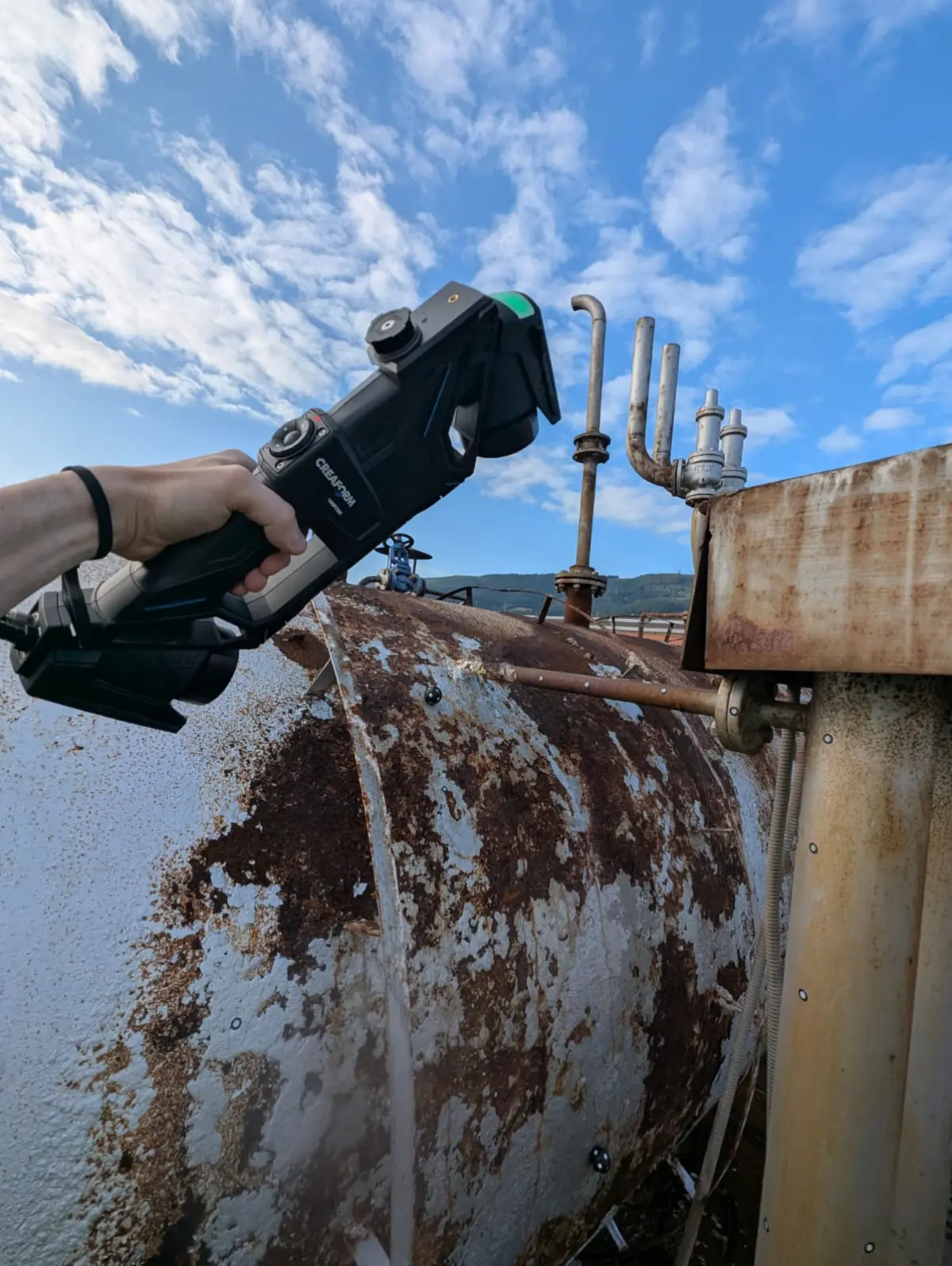
We scan the part, capturing its complete geometry as a point cloud. Depending on complexity, a part can generate between 500,000 and several million points. The accuracy of our portable scanner (Creaform HandyScan MAX) is ±0.15 mm with a resolution of 0.04 mm, allowing us to capture details such as chamfers, fillet radii, threads and surface textures. If the part is especially large or installed on a machine, we can perform complete facility 3D scanning for dimensional context.
The raw point cloud needs processing: we eliminate noise, close gaps caused by hard-to-access areas, and generate a polygonal mesh (STL/OBJ) that represents the part's surface as a set of triangles. If you want to understand in detail how the complete journey from point cloud to CAD model is traversed, we explain it in a dedicated article. This step is crucial for worn parts, because this is where we decide, together with the client, whether to model the part as-is or compensate for wear to recover the nominal geometry.
This is the core of the reverse engineering work. Over the polygonal mesh, our technicians build a native CAD model (STEP, IGES, Parasolid, or whatever native format the client needs: Solid Edge, AutoCAD). It is not an automatic conversion: real features are modeled —extrusions, revolutions, pockets, patterns— interpreting the original design intent. Symmetries are defined where they exist, radii are regularized and geometric constraints that give mechanical sense to the part are applied. The result is an editable model, not just a shell.
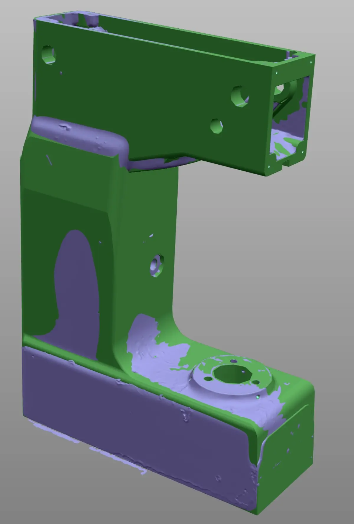
We compare the generated CAD model with the original scan mesh to verify deviations. We generate a color map that graphically shows where the model fits and where there are differences, and justify each deviation (for example, an area where we decided to compensate for wear). The verification report always accompanies the final deliverable.
If the goal is to manufacture the part, the 3D model is not enough: you need dimensioned 2D drawings with tolerances, surface finishes, material specifications and manufacturing notes. At PROMECAD we generate complete drawings to ISO standards, ready to send to the workshop. If the client needs CNC files, we also generate the appropriate formats (DXF, DWG, STEP for CAM).
What deliverables does the client receive?
One of the aspects our clients value most is the clarity of the deliverables. When we complete a reverse engineering project, the standard package includes:
- Parametric 3D model in whatever format the client needs (STEP, IGES, Solid Edge, AutoCAD). It is a native, editable model with a feature tree.
- Polygonal mesh from the processed scan (STL, OBJ) as a dimensional reference of the part's actual condition.
- Dimensioned 2D drawings (PDF, DWG, DXF) with tolerances, surface finishes and bill of materials, ready to send to the workshop.
- Dimensional verification report with a deviation map between the CAD model and the original scan.
- Manufacturing files (DXF for laser cutting, STEP for CNC machining, STL for 3D printing), if the project requires it.
- Technical report with material recommendations, manufacturing process and relevant notes.
The depth of the deliverables depends on the client's needs. There are projects where only the 3D model is needed for simulation, and others where full manufacturing documentation is required because the part goes directly to machining. In the initial phase of each project we define exactly what will be delivered, the deadlines and the budget. If you want to learn more or consult us about a specific case, you can write to us from our contact page.
Real cases: reverse engineering in industry
Theory is fine, but where the value of reverse engineering is truly understood is in real projects. We share three anonymized but representative cases from our work as a reverse engineering company with 3D scanners in Spain.
Case 1: Centrifugal pump impeller for a chemical plant
Sector: Chemical industry — Part: Closed impeller for centrifugal pump, 320 mm diameter, stainless steel casting.
Problem: The original impeller had been in service for 18 years and showed severe blade erosion. The pump manufacturer had been absorbed by another group and no longer supplied spare parts for that model. Buying a complete new pump meant a cost of over 35,000 euros and a 14-week delivery time.
Solution: We scanned the impeller with our Creaform HandyScan MAX (accuracy ±0.15 mm, resolution 0.04 mm). The CAD modeling was particularly delicate because the blade profiles had to be reconstructed by compensating for erosion. We worked with the client's maintenance team to define the nominal profile based on the least damaged areas and the pump's original performance curve. We delivered a STEP model, 2D drawings and documentation for precision casting in CF8M (equivalent to AISI 316).
Result: The part was manufactured at a local foundry in 4 weeks, at a cost below 40% of the new replacement. The pump recovered its nominal performance.
Case 2: Forming tooling for a 600-ton press
Sector: Automotive (Tier 2) — Part: Stamping punch and die in tool steel, complex geometry with variable radii.
Problem: The tooling was over 25 years old and had undergone several repairs. The original drawings existed but on paper, incomplete and with illegible dimensions. The client needed to manufacture a new replacement set because the current one had cracks and could not withstand further repairs. Without a reliable CAD model, CNC manufacturing was not feasible.
Solution: We performed the part digitization of both elements (punch and die) with a handheld laser scanner. The working surfaces were modeled as high-quality NURBS surfaces, while the structural areas were modeled as parametric solids. We cross-referenced the result with the old drawings to validate critical dimensions that were still legible. We delivered models in native Solid Edge format and STEP files for CAM programming.
Result: The client's toolmaker machined the new tooling directly from our models. The fit between punch and die was within tolerances on the first trial, without the need for manual adjustments.
Case 3: Conveyor guides and supports for the food industry
Sector: Food processing — Parts: Set of 12 side guides and 8 conveyor belt supports in AISI 304 stainless steel.
Problem: A dairy products factory needed to extend a packaging line by replicating an existing conveyor section. The conveyor was designed and installed by a local company that had closed 10 years ago. There was no technical documentation for any of the parts. The client needed to manufacture identical parts for the new section, ensuring dimensional compatibility with the existing one.
Solution: We scanned all 20 parts on-site, on the production line itself, during a scheduled maintenance shutdown. In addition to the 3D part scanning of individual components, we scanned the complete section to capture relative positions and mounting points. We modeled all parts in CAD, generated individual drawings and an assembly drawing with position references.
Result: The parts were manufactured by laser cutting and CNC bending. The assembly of the new section was completed in a single shutdown day, without any unexpected adjustments. The client has since commissioned us to document other line sections as a preventive measure for future expansions or breakdowns.
When is it worth it and when is it not?
It would be dishonest to say that reverse engineering is the solution for everything. There are situations where it is clearly worth it and others where it does not make sense:
It is worth it when:
- The part is critical for production and there is no supply alternative.
- The machine downtime cost far exceeds the cost of the reverse engineering project.
- You need to manufacture multiple units in the future (the CAD model pays for itself with each replica).
- You want to improve or adapt an existing design that works but needs optimization.
- You need to document critical parts or equipment as a contingency plan before they fail.
It may not make sense when:
- The part is a standard commercial component (bearing, O-ring, fastener) that you can buy from a catalog.
- The original manufacturer still exists and can supply the replacement at a reasonable price and lead time.
- The part is simple enough that it can be dimensioned with a caliper in 10 minutes and does not need a 3D scan.
At PROMECAD we always carry out this preliminary assessment with the client. When we receive an inquiry, the first thing we analyze is whether reverse engineering is truly the best solution or whether there is a simpler path. That honesty has earned us the trust of clients who have been working with us for years.
Why choose a specialized company?
How industrial 3D scanning works at the hardware level is something anyone with technical training can learn. The difference lies in what happens after the scan: interpreting the geometry, making decisions about wear and tolerances, CAD modeling with manufacturing criteria, and generating useful documentation.
At PROMECAD we have been designing mechanical components for industry for over 20 years. That technical experience is what makes the difference in our 3D scanning services: when we scan a part, we do not just see geometry — we see functionality, assembly conditions, manufacturing processes and potential improvements. It is the combination of scanning with state-of-the-art equipment and engineering judgment that turns a reverse engineering project into a truly useful deliverable.
We operate from Erandio (Bizkaia), but we provide services throughout northern Spain and, when the project requires it, we travel to any point on the peninsula. Our industrial 3D scanning equipment is portable: we can scan at your plant, your workshop or our facilities, whichever is most practical for each case.
Conclusion
Reverse engineering with 3D scanning is not a technology of the future: it is a tool that is solving real problems in factories of all kinds, today. If you have a part without documentation, a spare part that is impossible to obtain, or a design that needs updating, the Scan to CAD workflow gives you the complete technical documentation to manufacture, improve or document.
At PROMECAD we have converted hundreds of physical parts into CAD models ready for manufacturing. Every project is different, and that is why we work on a case-by-case basis, adapting the process to your real needs and not the other way around.
Tell us about your case and we will tell you how we can help. You can write to us from our contact page or call us directly. We will respond within 24 hours with an initial assessment.