November 27, 2025
3D Scanning in the Automotive Industry: Real Applications in Quality Control, Tooling and Product Development
The automotive industry operates with tight tolerances, demanding deadlines and a supply chain where any dimensional deviation is amplified throughout the assembly phases. In this context, 3D scanning for the automotive industry has become a standard tool for component manufacturers, die makers and tooling shops. It is not an experimental technology: it is a proven solution that solves real problems in quality control, tooling documentation and reverse engineering. In this article we review the real-world applications we see in our daily work with the sector.
Why the automotive industry needs 3D scanning
As in aeronautics, automotive component manufacturing combines three factors that make 3D scanning especially relevant: very tight dimensional tolerances (in the order of tenths of a millimeter for many parts), high production volumes (where a deviated tool can generate thousands of out-of-spec parts) and traceability requirements demanded by OEMs across the entire supply chain.
Traditional dimensional control methods —gauges, go/no-go calipers, point measurements with probes— remain valid, but have a fundamental limitation: they only measure discrete points. A 3D scanner captures the complete geometry of the part, generating millions of points in minutes. This allows detecting not only whether a dimension is out of tolerance, but exactly where the deviation is occurring, how extensive it is and in which direction it tends. For a detailed comparison between both approaches, we recommend our article on 3D scanner vs CMM (coordinate measuring machine).
Additionally, the portability of current scanners allows bringing metrology directly to the production floor, instead of having to transport parts to a climate-controlled measurement room. This is especially valuable for tooling weighing hundreds of kilograms or for inspections that must be performed without removing the part from the line.
Dimensional quality control in manufacturing
3D scanning for automotive quality control covers everything from first article validation to periodic inspection during series production. Each phase has its own particularities.
Verification of stamped parts
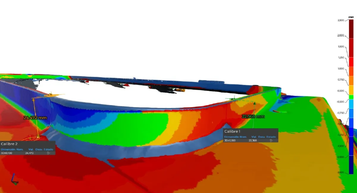
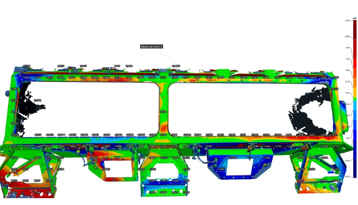
Stamped sheet metal parts are the most common in a vehicle's structure and body. Their geometry combines freeform surfaces with functional zones (positioning holes, welding surfaces, mating areas) that must meet strict tolerances. 3D scanning of body panels for dimensional control and stamped components generates a complete deviation map showing, point by point, how far the real part deviates from the nominal CAD.
This analysis is especially useful during the die try-out phase: the first stamped parts rarely come out perfect the first time, and the deviation map tells the die maker exactly where and how much to correct the tooling. The same applies when, after thousands of strokes, parts begin to show trends suggesting die wear. We go deeper into this topic in our article on 3D scanning of molds and dies.
Inspection of injection molded plastic components
Dimensional control of plastic components in the automotive industry presents an additional challenge: plastic shrinks and deforms as it cools, and this deformation is not always uniform or predictable. Interior components (door panels, consoles, HVAC ducts) and exterior components (bumpers, spoilers, headlight housings) must fit precisely within the vehicle assembly.
3D scanning allows verifying the complete injection molded part, including mating areas, fixing clips and contact surfaces with adjacent parts. If the part is out of tolerance, the deviation map helps determine whether the problem is in the mold, the injection parameters (temperature, pressure, cycle time) or the material shrinkage. For more context on this technique, check our article on dimensional quality control with 3D scanner.
Prototype and first article validation
During the development phase, 3D scanning for automotive part homologation allows verifying whether prototypes and first production parts meet specifications before approving serial production. This is a critical moment: detecting a problem here avoids having to fix it when the line is already running, with the cost that implies.
3D digitization of vehicle prototypes is also used to verify fit between components from different suppliers. When several parts from different Tier 1 suppliers must be assembled together in the vehicle, scanning each one and simulating the digital assembly allows anticipating fit problems before they reach the OEM assembly line.
Digitization of production tooling
Tooling is the heart of automotive production. Dies, stamping tools, welding fixtures, verification gauges: these are the elements that ensure each part comes out the same as the previous one. Digitally documenting them is not a luxury, it is an operational necessity.
Stamping dies and welding fixtures
3D scanning of tooling and stamping dies has two main applications. The first is wear control: comparing the current state of the die against its nominal CAD (or against a previous scan) to quantify how much material has been lost and where. The second is documentation: many tools that have been in production for years have no up-to-date CAD documentation, either because they were modified with manual touch-ups or because the original drawings were lost.
In welding fixtures (jigs, positioning templates), 3D scanning allows verifying that support points and locators are where they should be. A fixture that has deformed slightly after thousands of welding cycles can cause deviations in the welded assembly geometry that, when accumulated, exceed the OEM tolerance.
Gauges and assembly fixtures
Verification gauges and assembly fixtures also wear and deform with use. A gauge that is not in proper condition can approve parts that are out of tolerance, or reject parts that are correct. Periodic scanning of these elements allows verifying that they remain reliable and, if they are not, generating the necessary documentation to manufacture a new one.
If you want to learn about more situations where 3D scanning adds value on the shop floor, we recommend our article about the 5 situations where your factory needs 3D scanning.
Reverse engineering of discontinued parts
Reverse engineering of discontinued automotive parts is a regular reality in the sector. Vehicle manufacturers are required to supply spare parts for a certain period, but after that time, parts stop being manufactured. When a discontinued component fails in a vehicle that is still in service —whether a classic car, an industrial vehicle or a transport fleet— reverse engineering is often the only way to obtain a replacement.
The process consists of scanning the existing part (even if worn or damaged), reconstructing the parametric CAD model with technical judgment and generating the necessary manufacturing documentation. At PROMECAD, our technicians work in Solid Edge and AutoCAD to model parts ranging from brackets and bushings to complete mechanism housings. The key is not to simply copy the scanned geometry, but to interpret the original design intent: regularize surfaces, define symmetries where they exist and assign tolerances consistent with the part's function. For more detail on this process, check our complete guide on reverse engineering with 3D scanning.
This service is especially in demand from classic car workshops, fleet maintenance companies and, increasingly, Tier 2 manufacturers who need to reproduce tooling components whose documentation has been lost.
PROMECAD and the Basque automotive industrial fabric
The Basque Country has one of the highest densities of automotive component manufacturers in all of Spain. Dozens of Tier 1 and Tier 2 companies operate within a radius of just a few kilometers, producing everything from stamped and machined parts to welded assemblies and plastic components for the major European OEMs.
PROMECAD operates from Erandio (Bizkaia), at the center of this industrial fabric. We have been working in industrial mechanical design for over 20 years, and since 2024 we have incorporated state-of-the-art 3D scanning equipment to meet the needs of our clients in the automotive and other sectors. Our portable Creaform HandyScan MAX scanner (accuracy ±0.15 mm, resolution 0.04 mm) allows us to work directly at our clients' plants, without the need for parts or tooling to leave the factory.
Physical proximity matters in the automotive industry, where deadlines are tight and responsiveness makes the difference. But what truly adds value is the combination of scanning capability with technical design judgment: when we scan a tool, we do not just capture geometry, but understand the function of each surface, the manufacturing requirements and the implications of a dimensional deviation. That technical experience is what allows us to deliver directly applicable results, not just raw data.
Case study: digitization of welding fixture for assembly line
Case: Digitization and verification of robotic welding fixture
Sector: Automotive (Tier 1) — Tooling: Spot welding fixture for body subassembly, steel structure with 24 locators and 8 adjustable support points.
Situation: The client had two identical fixtures for the same part reference, used in alternating shifts. After several months of production, they detected that parts welded in one of the fixtures showed slightly higher dimensional deviations than those from the other. The suspicion was that the fixture had deformed, but manual probe measurements were inconclusive because they could only verify individual points.
Process: We scanned both complete fixtures directly in the welding cell, during the weekend shift changeover. We captured the position of all locators, support points and reference surfaces. We aligned both scans against the nominal CAD and generated comparative deviation maps. The analysis revealed that the problematic fixture had a 0.4 mm deformation in the central base area, probably caused by an accidental impact during a reference changeover. This deformation was displacing three locators enough to cause the deviation the client was detecting in the parts.
Result: With the deviation report, the client's maintenance team was able to correct the deformation locally, repositioning the affected elements and verifying the result with a second scan. The fixture returned to producing parts within tolerance without the need to manufacture a new one. The entire process was completed over a weekend, without affecting production.
Frequently asked questions
What accuracy does 3D scanning have for quality control in the automotive industry?
With our Creaform HandyScan MAX scanner we achieve an accuracy of ±0.15 mm and a resolution of 0.04 mm. This accuracy is sufficient for most dimensional control applications in the automotive industry, including verification of stamped parts, injection molded plastic components and production tooling. For parts with tighter tolerances, 3D scanning is used as a fast screening tool, complementing point measurements with CMM.
Can scanning be done directly on the production line?
Yes. Our scanning equipment is completely portable, allowing us to work directly on the shop floor. We scan parts on verification tables next to the line, tooling mounted on presses or welding cells, and assemblies at the actual assembly stations. We only need the part or tooling to be accessible and the area to be sufficiently lit.
What file formats are delivered for integration with OEM systems?
We deliver in industry-standard formats: STEP, IGES and Parasolid for 3D models; STL and OBJ for polygonal meshes; DXF and DWG for 2D drawings; and 3D PDF for interactive deviation reports. If the client works with Solid Edge or AutoCAD, we deliver in native format. Inspection reports are generated in formats compatible with standard automotive quality management systems.
How long does an automotive 3D scanning project take?
The scanning itself is fast: a medium-sized part is captured in 15–30 minutes. The total project timeline depends on scope: a dimensional inspection with deviation report can be ready in 2–3 working days, while a complete reverse engineering project with parametric CAD model and drawings may require 1–3 weeks depending on geometry complexity. For cost guidance, check our industrial 3D scanning pricing guide.
Let's talk about your automotive project
If you need to verify parts, document tooling, recover discontinued spare parts or implement a dimensional control program with 3D scanning at your plant, we can help.
At PROMECAD we combine over 20 years of experience in industrial mechanical design with state-of-the-art 3D part scanning equipment. We travel to your plant, work with the deadlines the automotive industry demands and deliver directly applicable results. We operate from Erandio (Bizkaia), at the center of the Basque automotive cluster, and provide service throughout northern Spain and, when the project requires it, anywhere in the peninsula.
Tell us what you need. Write to us from our contact page or call us directly. We will respond within 24 hours with an initial assessment.