March 10, 2026
How to digitize an industrial part without original drawings
You have a critical part on your production line. It has been working for years, but the manufacturer no longer exists, the drawings were lost long ago and now you need to replicate it, modify it or simply document it. This is a much more common situation than it might seem. In this guide we explain, step by step, how to digitize an industrial part without any prior technical documentation, what technology is used, what deliverables you can expect and how much it approximately costs.
Why so many industrial parts have no drawings
Before getting into the technical process, it is worth understanding why this situation is so common. It is not a matter of negligence: there are structural reasons why millions of parts in factories across Spain lack digital documentation.
Old factories without digitized documentation
Many industrial plants in the Basque Country and the rest of Spain have been operating for 30, 40 or even 50 years. Their equipment was designed in an era when CAD either did not exist or was not widespread. The drawings, if they ever existed, were made on paper, in A0 format, and over time they have deteriorated, been misplaced or simply become obsolete after successive workshop modifications. In practice, what is installed in the machine no longer matches what those drawings reflect —if anyone even knows where they are—.
Handmade or workshop-modified parts
It is common to find components that never had a formal drawing. They were manufactured directly in the workshop, from a sketch or the verbal instructions of an experienced operator. Other times the part did have original drawings, but was modified on the fly —a weld here, a recess there— and nobody documented those changes. The result is the same: the part exists, it works, but there is no digital file that describes it.
Defunct suppliers or discontinued references
Another very common case: the part was supplied by a manufacturer that has closed, been acquired by another group or simply stopped manufacturing that reference. You contact the supplier and the answer is that they no longer have technical documentation for that model. The only reference left is the physical part you have in your hand, possibly worn. This situation is especially common in the aeronautics sector, where legacy components from aircraft that have been in service for decades need to be replicated without original documentation and with very demanding traceability requirements. If you identify with any of these situations, we recommend our article about the 5 situations where your factory needs 3D scanning, where we cover other similar scenarios.
What options do you have to digitize a part without documentation
When there are no drawings, there are basically three paths to obtain the dimensional information of a part. Not all of them work for every situation.
Manual measurement with calipers and micrometers (and their limits)
This is the first option any workshop considers. You take a caliper, a micrometer, a radius gauge and measure dimension by dimension. It works reasonably well for simple prismatic parts —a stepped shaft, a flange with a regular bolt pattern, a flat plate—. But as soon as the geometry gets complex (curved surfaces, blade profiles, molds, organic shapes, parts with dozens of interrelated dimensions), manual measurement becomes slow, error-prone and, in many cases, simply unfeasible. You cannot measure the exact profile of a pump impeller or the working surface of a stamping die with a caliper.
Industrial 3D scanning: the precise and fast alternative
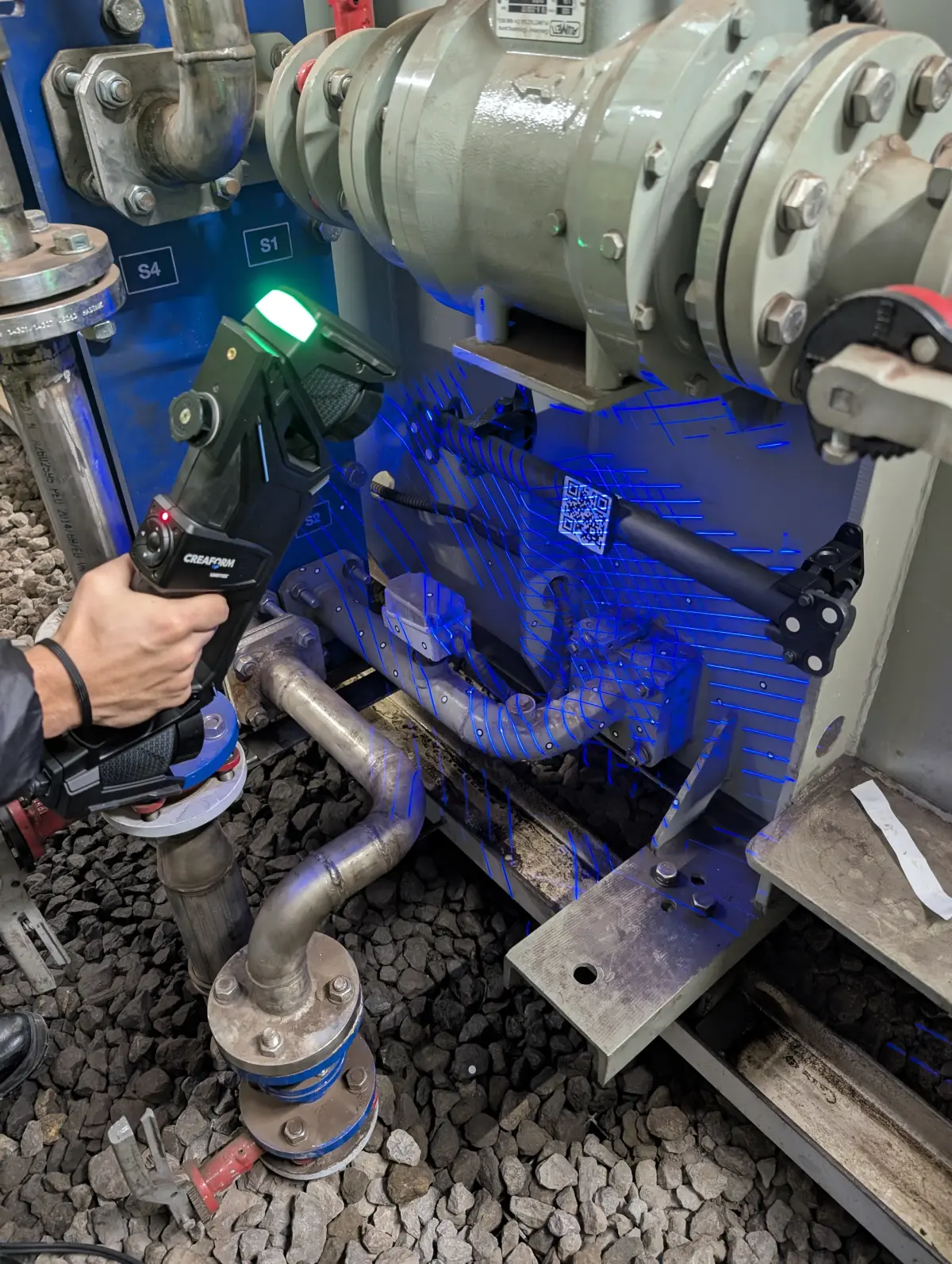
3D part scanning solves the limitations of manual measurement in one stroke. An industrial-grade 3D scanner captures millions of points on the part surface in a matter of minutes, generating a complete digital representation of its entire geometry. It does not matter if the part has complex shapes, accessible internal cavities, threads, ribs or freeform surfaces: the scanner captures it all.
At PROMECAD we use the Creaform HandyScan MAX, a portable laser scanner with a volumetric accuracy of ±0.15 mm and a mesh resolution of 0.04 mm. It is the right tool for small and medium-sized industrial parts (from a few centimeters to 2-3 meters). For larger parts or complete assemblies, we combine portable scanning with our Trimble X7 terrestrial scanner to capture the dimensional context of the installation. If you want to understand the complete process in more detail, check our guide on how industrial 3D scanning works.
Photogrammetry: when it makes sense and when it does not
Photogrammetry (3D reconstruction from photographs) is another technique that is sometimes considered. It can be useful for large objects where absolute accuracy is not critical —for example, documenting the general shape of a structure or a tank—. But for mechanical parts where you need to manufacture a replacement with tolerances of tenths of a millimeter, photogrammetry does not achieve the necessary accuracy. In the industrial context we are discussing in this article, laser 3D scanning is the reference technology.
The step-by-step process: from the physical part to the CAD file
Digitizing a part is not simply scanning it and pressing a button. Scanning is the first step of a process that requires technical knowledge, specialized software and mechanical design experience. This is how we work at PROMECAD:
Before scanning, we analyze the part: material, surface finish, approximate dimensions, condition and critical areas. If the part is worn or broken, we identify the affected areas and decide, together with the client, whether the goal is to model the part in its current state or reconstruct the original geometry. This preliminary assessment is essential because it determines all subsequent project decisions.
We scan the part, capturing its entire surface as a cloud of millions of three-dimensional points. Depending on complexity and size, scanning can take between 10 minutes and a couple of hours. If the part has cavities or hard-to-reach areas, we make multiple passes from different angles. If necessary, we apply reference markers (adhesive targets) to ensure accuracy on large parts or those with repetitive geometry.
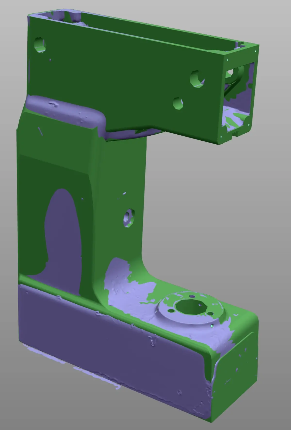
The raw point cloud needs processing: we remove noise, close small gaps caused by inaccessible areas and generate a polygonal mesh (STL) that represents the part surface as a set of triangles. This file is already a faithful digital representation of the part, but it is not yet an editable CAD model. It is the intermediate step between the physical world and the parametric model.
This is the step that makes the difference and where our mechanical design knowledge comes in. Over the polygonal mesh, we build a native CAD model —with real features: extrusions, revolutions, shells, patterns, chamfers— interpreting the original design intent of the part. It is not an automatic conversion: it is expert manual work that requires understanding how and why that part was designed the way it was. If you want to delve deeper into this process, we explain it in detail in our complete guide on reverse engineering with 3D scanning.
Once the CAD model is complete, we compare it against the original scan mesh to verify deviations. We generate a color map (deviation report) that graphically shows where the model matches the real part and where there are intentional differences (for example, areas where we compensated for wear). This report always accompanies the final deliverable and provides complete traceability of the process.
What deliverables you receive when digitizing your part
One of the aspects our clients value most is the clarity of what they will receive. When we complete a digitization project, the standard deliverable package includes:
3D parametric model (STEP, Solid Edge, AutoCAD)
The main deliverable: a native, editable CAD model with a feature tree. We deliver it in whatever format the client needs: STEP or IGES as a universal format, or in the native format of their software (Solid Edge, AutoCAD, etc.). It is a real model, not a shell: you can modify it, dimension it, simulate it or send it directly for machining.
Dimensioned 2D drawings with tolerances
If the goal is to manufacture the part, the 3D model is not enough: you need 2D drawings with dimensions, dimensional and geometric tolerances, surface finishes and material specifications. We generate complete drawings according to ISO standards, ready to send to any CNC machining shop, foundry or laser cutting facility.
Deviation report (if the part is worn)
When the source part shows wear, breakage or deformation, we deliver a dimensional report showing the differences between the actual condition (scan) and the nominal geometry (reconstructed CAD model). It is an essential document to justify the reconstruction decisions and for the client to understand exactly what was done and why.
Case study: 1980s machinery part with no replacement available
Transmission shaft for packaging line (food industry)
Situation: A meat products factory in Bizkaia had a packaging line from the 1980s. The main transmission shaft —a machined AISI 316 stainless steel part, with keyway, three-diameter stepping and threads at both ends— showed severe wear in the seal area. The machine manufacturer had closed more than 15 years ago. There were no drawings, no CAD model and no replacement reference.
What we did: We scanned the complete shaft with the HandyScan MAX. We identified the wear zones (the seal area and a slight bending in the central stepping) and the intact zones. From the symmetries, functional dimensions (bearing housings, standardized keyway) and complementary measurements with a micrometer at key points, we reconstructed the complete nominal geometry. We delivered a STEP model, dimensioned 2D drawings with ISO tolerances and a report documenting the deviations of the worn shaft against the reconstructed nominal.
Result: The client's machine shop manufactured the new shaft in 5 working days. The part fitted perfectly in the machine the first time, without any unexpected adjustments. The total project cost (scanning + modeling + drawings) represented less than 20% of what it would have cost to replace the entire machine.
If you are wondering how much an industrial 3D scanning service costs, in that article we break down approximate rates by project type so you have an order of magnitude before requesting a quote.
How long it takes and what we need to get started
Timelines depend on the complexity of the part, but as an approximate reference:
- Simple part (shaft, flange, bracket): 2-4 working days from receipt or on-site scanning.
- Medium complexity part (housing, impeller, tooling): 5-8 working days.
- Complex part or assembly (stamping die, mold, multi-component mechanism): 8-15 working days.
To get started, all we need is the physical part (or access to it at your plant). If the part is small and easy to transport, you can send it to our facilities in Erandio (Bizkaia). If not, we travel to your location with our portable industrial 3D scanning equipment. We regularly operate in the Basque Country and throughout northern Spain, and for projects that require it, we travel anywhere in the peninsula.
You do not need to know anything technical beforehand. We just need you to tell us what part it is, what you need it for and what you want to do with it (replicate it, modify it, document it). We take care of defining the technical approach and proposing a fixed-price quote.
Frequently asked questions
Can a broken or worn part be digitized?
Yes. The part is scanned in its current condition and, during CAD modeling, the damaged areas are reconstructed by interpreting the original geometry from the intact zones: symmetries, patterns, fillet radii and dimensional references from the assembly. This is a task that requires mechanical design experience, not just scanning expertise.
What accuracy is achieved without reference drawings?
With the HandyScan MAX we achieve a volumetric accuracy of ±0.15 mm and a mesh resolution of 0.04 mm. This is more than sufficient for the vast majority of mechanical manufacturing applications. In areas where maximum precision is required (bearing housings, h7/H6 fits, etc.), we complement the scanning with point measurements using conventional metrology instruments.
Do I need to bring the part to your facilities?
Not necessarily. Our scanning equipment is fully portable: we can scan at your plant, your workshop or your warehouse, without interrupting production. If the part is small and easy to transport, you can also send it or bring it to our facilities in Erandio (Bizkaia).
Can I manufacture directly with the file you deliver?
Yes. We deliver native CAD models (STEP, IGES, Solid Edge, AutoCAD) and dimensioned 2D drawings with tolerances, ready to send to a CNC machining shop, foundry, laser cutting facility or any other manufacturing process. If you need specific files for your process (DXF for cutting, STL for 3D printing), we include those as well.
Next step: tell us about your case
At PROMECAD we have over 20 years of experience in industrial mechanical design. That experience is what allows us, when we scan a part, to not only see geometry, but understand functionality, assembly conditions and manufacturing process. It is the difference between delivering a 3D file and delivering a complete solution, ready to manufacture.
If you have a part without drawings that you need to replicate, modify or document, tell us about your case. We evaluate each inquiry individually and honestly tell you whether 3D scanning is the best solution for your specific case or if there is a simpler path.
Request a no-obligation quote or call us directly at +34 94 406 42 83. We will respond within 24 hours with an initial assessment.