January 30, 2026
Scan to BIM: how to digitize an existing industrial plant for renovation or expansion projects
Your plant has been operating for 20 or 30 years. Renovations, expansions and modifications have been carried out that were never documented. The original drawings, if they exist, do not reflect reality. And now comes an expansion project, a facility renovation or an audit that requires up-to-date as-built documentation. The problem is that nobody knows exactly what is in there. This is what Scan to BIM solves: capturing the entire facility with a 3D laser scanner and converting that capture into a navigable, measurable BIM model usable for any subsequent project. In this article we explain the entire process, step by step, with the technical specifications of our equipment and the most common delivery formats.
The problem: plants operating for decades without updated drawings
It is a situation we encounter with surprising frequency. Industrial plants with 15, 20 or 40 years of history accumulate modifications that nobody documented: a piping line that was relocated during a maintenance shutdown, equipment that was replaced with a different-sized unit, a steel structure that was reinforced to support a new load, ventilation ducts that were added during a partial renovation.
The result is a real facility that does not resemble the drawings on file —if there are any drawings at all—. And when the time comes to plan a renovation, a production line expansion or the installation of new equipment, those responsible for the project face an information gap that can cause costly errors: clashes with existing piping that was not documented, insufficient headroom, cable routing that conflicts with structure, or simply the impossibility of carrying out detail engineering without knowing what is actually in the plant.
We have described this problem in more detail in our article on the 5 situations where your factory needs 3D scanning, where the plant without updated drawings is one of the most common scenarios.
What is Scan to BIM (and why is it different from a simple scan)
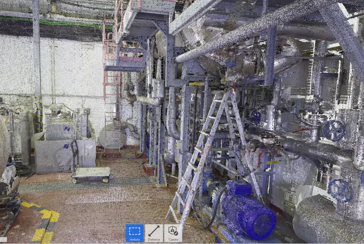
This point deserves clarification because it generates confusion. Scanning an industrial plant with a 3D laser scanner produces a point cloud: millions of XYZ coordinates that represent with millimetric precision the geometry of everything the scanner captured. That point cloud is, in itself, a useful tool: it allows taking measurements, visualizing the facility in 3D and detecting elements that do not appear in existing documentation.
But a point cloud is not a BIM model. A 3D point cloud is a three-dimensional photograph of reality: it contains geometry, but it does not contain information. It does not distinguish a pipe from a ventilation duct, it does not know the diameter of each element, it has no layers or categories. It is a massive set of points in space.
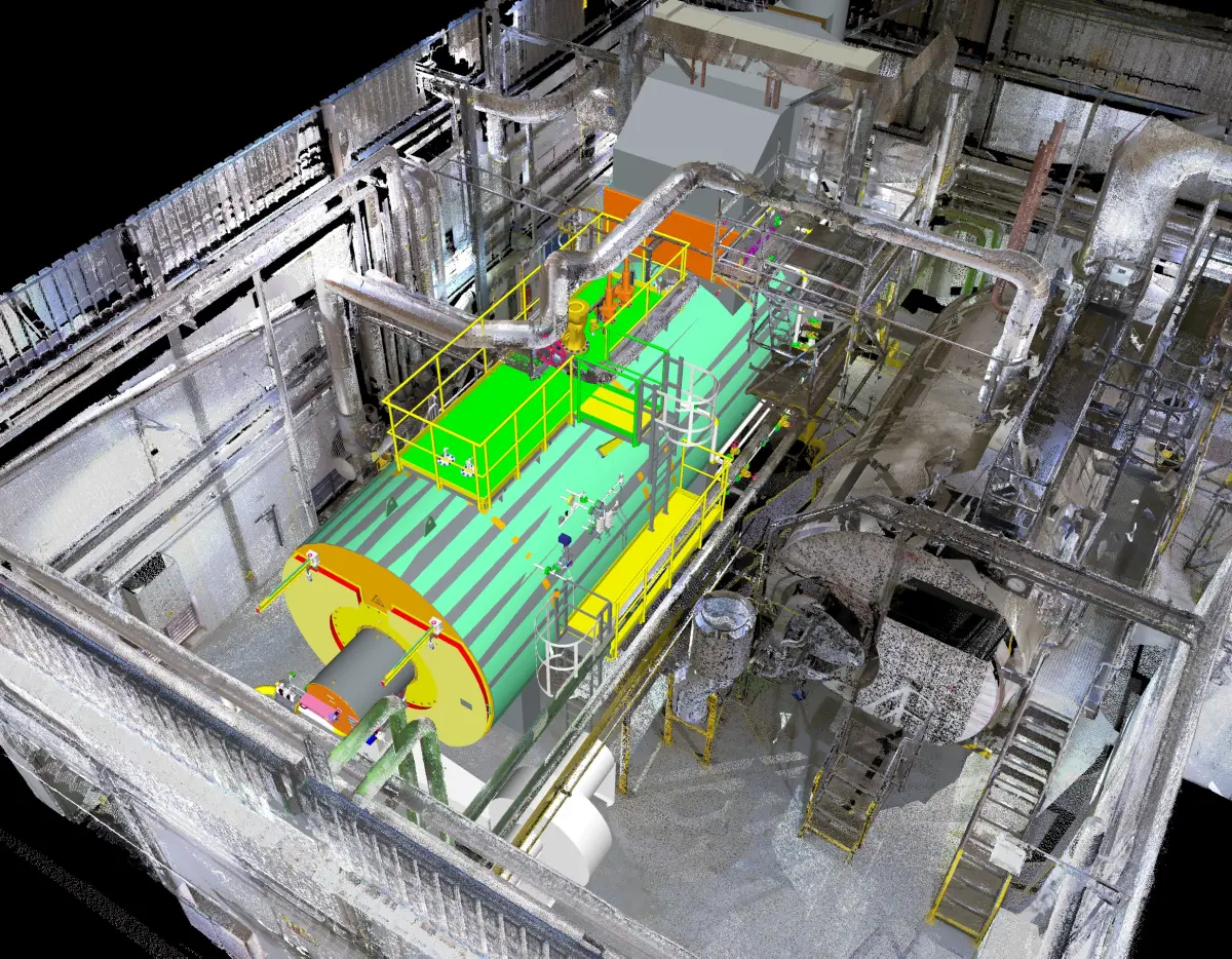
Scan to BIM is the complete process: capturing the point cloud with the laser scanner and, from it, building a BIM (Building Information Modeling) model where each element is identified, categorized, dimensioned and positioned according to reality. It is the difference between having a photo of your plant and having an intelligent plan of your plant. If you want to delve deeper into how the journey from point cloud to model works, we recommend our guide on how to convert a point cloud into a CAD model.
The step-by-step process
At PROMECAD we carry out industrial facility 3D scanning projects following a structured workflow that guarantees the quality of the final result. These are the phases:
1. Scan planning
Before taking equipment to the plant, we need to understand what will be captured and for what purpose. We visit the facility (or analyze available documentation) to define the scope: which areas are to be scanned, what level of detail is needed, which are the hard-to-access areas, whether there are safety or operational restrictions that condition the work. In this phase we also define the approximate number of scanning stations needed and the fieldwork logistics.
Planning is critical because a poorly planned scan generates gaps in the point cloud, areas without coverage and, ultimately, an incomplete model that requires returning to the plant. Investing time in this phase saves problems in all subsequent ones.
2. Capture with terrestrial laser scanner
Fieldwork is carried out with our Trimble X7 terrestrial laser scanner, equipment specifically designed for capturing industrial spaces and facilities. Its main specifications are:
- Measurement range: from 0.6 to 80 meters, allowing capture from confined spaces to high-bay buildings.
- Accuracy: approximately 4 mm at 10 meters distance, sufficient for as-built modeling of industrial facilities.
- Auto-leveling and automatic registration: the Trimble X7 incorporates an electronic compensator and automatic registration between stations, which speeds up fieldwork and reduces alignment errors.
- Color capture: each point is captured with color information (RGB), which facilitates subsequent interpretation of the point cloud.
Each scanner position (station) captures millions of points in just a few minutes. To cover a complete facility, multiple stations are set up —from dozens to hundreds in large plants— that overlap each other to ensure total coverage. The equipment is portable, requires no fixed installation and does not interfere with normal plant operations: scanning can be performed while the facility is in operation.
For those wondering about the differences between scanning technologies, we have prepared a detailed comparison between structured light 3D scanner and laser scanner, which explains when each technology is most appropriate.
3. Registration and station alignment
Once fieldwork is complete, the individual point clouds from each station must be unified into a single global point cloud. This process is called registration and consists of aligning all stations in the same coordinate system. The Trimble X7 performs much of this registration automatically in the field, but in complex projects a subsequent refinement is done in the office to ensure the overall accuracy of the dataset.
The result is a unified point cloud representing the entire scanned facility, with millimetric precision and no discontinuities between areas. This point cloud is already a deliverable in itself: it can be navigated, measured and shared with any project stakeholder.
4. Point cloud cleaning and classification
The raw point cloud contains everything that was in the scanner's field of view during capture: the facility, but also people, vehicles, temporarily stored materials, reflections and noise. Before starting modeling, we clean the cloud by removing unwanted elements and classify the points by category (structure, piping, equipment, cable trays, ducts) to facilitate subsequent modeling work.
5. As-built BIM modeling
This is the phase that adds the most technical value and where the greatest portion of project time is concentrated. Over the clean, classified point cloud, our specialists build the BIM model element by element: steel or concrete structure, piping with diameters and identification, main equipment with dimensions and position, cable trays, HVAC ducts, platforms and stairs, and any other relevant element for the project.
The level of detail (LOD) is agreed with the client at the start of the project. It is not the same to produce an as-built model for a general building renovation (where LOD 200-300 is sufficient) as a model for clash detection in a petrochemical plant with high piping density (where LOD 350 or higher is needed). The LOD directly conditions the timeline and cost of the project, so it is a decision made collaboratively.
What can be captured
A common question from our clients is how far the laser scanner's capture capability extends. The short answer: virtually everything that is visible and accessible. In a typical digitization of existing industrial facilities project, the elements captured and modeled include:
- Structure: columns, beams, trusses, floor slabs, walls, visible foundations, platforms and stairs.
- Piping: main and secondary process lines, utilities (water, steam, compressed air, gas), with diameters, supports and fittings. Piping digitization and 3D routing is one of the most in-demand applications in process plants.
- Main equipment: tanks, heat exchangers, pumps, compressors, boilers, reactors, with real positioning and dimensions.
- Cable trays: tray routes, dimensions and relative positions to other elements.
- HVAC ducts: air conditioning, ventilation and extraction, including sections, reductions and connections to equipment.
- Architectural elements: enclosures, roofing, doors, openings, floor levels and clear heights.
The only real limit is the line of sight: the scanner captures what it can see. Hidden areas (the interior of a closed piece of equipment, a pipe embedded in a wall, an area behind an enclosure) are not captured and are documented as such in the final model.
Delivery formats
One of the aspects our clients value most is the flexibility of delivery formats. We adapt the project output to the software and workflow used by the client or the engineering firm that will develop the subsequent project. The most common formats are:
- Revit (.rvt): the de facto standard for BIM projects. It is the format requested by most engineering firms and contractors when they need an as-built model for renovation or expansion projects.
- AutoCAD Plant 3D: especially used in process plants for piping modeling and isometrics.
- Navisworks (.nwd/.nwc): for model review, clash detection and multi-discipline coordination.
- IFC (Industry Foundation Classes): open BIM exchange format, software-independent. Increasingly requested by public administrations and companies with OpenBIM policies.
- Navigable point cloud (.rcp/.rcs, .e57, .las): the processed and unified point cloud, ready to load into any compatible software. It is a deliverable complementary to the BIM model that allows the user to navigate through the original capture and take additional measurements.
- AutoCAD 2D (.dwg): for clients who need floor plans, sections and elevations in traditional 2D format, extracted from the BIM model.
For more information on budgets and factors influencing the cost of these projects, you can check our guide on how much an industrial 3D scan costs.
Main applications
Renovation and expansion projects
This is the most direct application. When a plant needs to expand a production line, install new equipment or renovate an area, the as-built model provides the exact dimensional basis to work on. The project engineering team can design the new installations directly on the existing model, with the certainty that the dimensions, heights, piping routes and structural positions are the real ones, not what drawings from 20 years ago say.
Clash detection before construction
One of the greatest savings that Scan to BIM provides is the ability to detect clashes before construction begins. By overlaying the design of the new installations on the as-built model, collisions with existing elements are identified that would have caused delays and cost overruns during construction: a new pipe that crosses where an existing cable tray runs, equipment that does not fit in the available height, a duct route that interferes with a beam.
Resolving these clashes in the model costs hours; resolving them on-site costs weeks and tens of thousands of euros.
As-built documentation for maintenance
Beyond capital projects, having an up-to-date as-built model improves day-to-day maintenance management. It allows locating valves, identifying piping routes, planning interventions with exact knowledge of what is there and facilitating training of new personnel. In plants with high staff turnover or with subcontracted maintenance operations, the as-built model becomes a permanent reference tool. This same approach to digitizing large spaces is applied with excellent results in the naval sector and shipyards, where capturing engine rooms and piping systems is fundamental for repair and retrofitting projects.
Case study: digitization of an industrial building for production line expansion
Metal component manufacturing building — 4,500 m²
Sector: Metal fabrication — Area: Main building of 4,500 m² with production area, storage zone and adjacent technical offices.
Situation: The company needed to expand an existing production line by incorporating two new large-format machines (press brake and laser cutter) that required special foundations, new utility connections (electricity, compressed air, fume extraction) and a partial reorganization of the layout. The building had been operating for 22 years and had undergone three partial renovations without documentation. The original drawings showed the 2004 layout, completely outdated.
Work performed: We scanned the complete building with the Trimble X7 over two working days, with the plant operational. 87 scanning stations were set up covering all areas, including the technical mezzanine where cable trays and extraction ducts ran. After registration and cleaning of the point cloud, we modeled the facility in BIM at LOD 300 detail level: complete structure, all piping and duct lines, exact position of existing machines, cable trays and the connection points for each utility.
Result: The project engineering team used the as-built model as a basis for designing the expansion. During the design phase, three critical clashes were detected that would have caused construction delays: an extraction duct that crossed through the area planned for the new foundation, a cable tray that prevented installation of the auxiliary overhead crane, and a compressed air pipe that did not appear on any drawing and would have been damaged during foundation work. All three clashes were resolved in the model before construction began.
Frequently asked questions
What is a 3D point cloud and how is it used in Scan to BIM?
A 3D point cloud is a set of millions of XYZ coordinates representing the real geometry of a space or facility. It is obtained using a terrestrial laser scanner that measures distances to thousands of points per second. In a Scan to BIM workflow, that point cloud is used as a dimensional reference to build a BIM model where each element is identified, categorized and dimensioned. The point cloud is the raw material; the BIM model is the final product.
How long does it take to complete a Scan to BIM project?
The timeline depends on the size and complexity of the plant. As a reference, an industrial building of 2,000 to 5,000 m² may require between 1 and 3 days of field scanning and between 2 and 4 weeks of BIM modeling, depending on the required level of detail (LOD). More complex plants, such as process facilities with high piping density, may need proportionally longer timelines. In the planning phase we always define a detailed schedule with intermediate milestones.
Can the plant be scanned while it is operating?
Yes. 3D laser scanning of process plants is routinely performed with the facility in normal operation. The scanner does not require contact with the facilities and does not interfere with production. Only standard safety measures (PPE, coordination with the plant manager) are needed and, in some cases, occasional access to restricted areas during scheduled maintenance shutdowns.
What level of detail (LOD) can be achieved in an as-built model?
The level of detail is defined at the start of the project according to the client's needs. The most common levels are LOD 200 (basic geometry and positioning, suitable for general planning), LOD 300 (precise geometry with real dimensions, valid for most renovation projects), and LOD 350 (includes connections and interfaces between elements, necessary for clash detection). The level is agreed based on the intended use of the model, balancing detail with timeline and cost.
Request an as-built scan of your plant
If you are planning a renovation, an expansion or simply need to document the actual state of your facility, the first step is to capture reality with the precision that only a 3D laser scanner can offer. At PROMECAD we work with the Trimble X7 for facility capture and complement it with our portable 3D scanning equipment for parts and equipment requiring higher resolution. We operate from Erandio (Bizkaia) and travel to any point in Spain.
Tell us about your project and we will prepare a tailored proposal. You can write to us from our contact page or call us directly. We will respond within 24 hours with an initial assessment.