January 9, 2026
3D Scanning in the Naval Sector: Shipyards, Repair and Retrofitting
The naval sector works with large-scale geometries, vessels that have been in service for decades without updated documentation, hard-to-access spaces, and drydocking schedules pushed to the maximum. In this context, 3D scanning in the naval sector and shipyards has become an essential tool for planning repairs, documenting the actual condition of a vessel, and executing retrofitting projects with confidence. In this article, we explain how it works, what applications it has, and why it represents a decisive advantage over traditional measurement methods.
Naval sector challenges that 3D scanning solves
Working in shipyards and on vessels presents challenges that do not exist in other industrial sectors. To understand why 3D scanning in the naval sector adds so much value, it is worth reviewing the common difficulties that technicians encounter in each project.
Large-scale geometries. A merchant vessel can measure between 80 and 300 metres in length. Documenting the actual geometry of a hull, a deck, or a complete hold with manual methods —tape measures, levels, plumb lines— is a slow process, prone to cumulative errors, and generates documentation that is difficult to interpret. 3D laser scanning captures millions of points with millimetre precision in a fraction of the time, providing a faithful digital representation of reality.
Absence of original documentation. Many vessels that now need repair or modification were built 20, 30 or even 40 years ago. In many cases, the original drawings have been lost, are incomplete, or do not reflect the modifications made throughout the vessel's service life. The situation is similar to what we describe in our article on how to digitise a part without drawings: when there is no documentation, 3D scanning is the only reliable way to obtain the actual geometry.
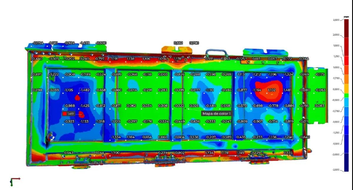
Corrosion and deformations. The marine environment is particularly aggressive. Hulls corrode, structures deform from cyclic loads, and steel loses thickness over the years. Knowing the actual condition —not the theoretical one from the original drawing— is fundamental for planning any intervention. 3D scanning allows deformations and thickness loss to be objectively quantified, comparing the current condition against the nominal design or against previous scans.
Confined spaces and difficult access. Engine rooms, ballast tanks, double bottoms and bilges are spaces where taking manual measurements is slow, uncomfortable and, in some cases, dangerous. 3D scanning captures these spaces quickly, reducing the time technicians need to spend in restricted access areas.
Limited drydocking periods. The time a vessel spends in dry dock is costly: each non-operational day represents significant losses for the shipowner. Any tool that shortens the data capture and planning phase has a direct impact on project profitability. We explain the general process of how this technology works in detail in our guide to industrial 3D scanning.
Applications of 3D scanning in the naval sector
Hull scanning for repair and modification
Digitising the hull of a vessel in dry dock is one of the most direct applications of 3D scanning in shipyards. Through multiple scan station setups with the terrestrial laser scanner, the complete geometry of the outer hull is captured, including the underwater body and the topsides. The resulting point cloud allows:
- Verifying deformations by comparing the actual geometry against the original lines plan or against a previous scan of the same vessel.
- Planning plate repairs with exact dimensions of affected areas, avoiding back-and-forth trips between the vessel and the fabrication workshop.
- Documenting condition before and after an intervention, creating a digital record that classification societies can review.
- Generating sections and plate developments of the hull plating to fabricate replacement pieces with the exact curvature.
The approach is very similar to what we use in scanning large industrial facilities: mass capture with laser scanner, automatic station registration, and generation of a navigable and measurable 3D model.
Engine room and machinery digitisation
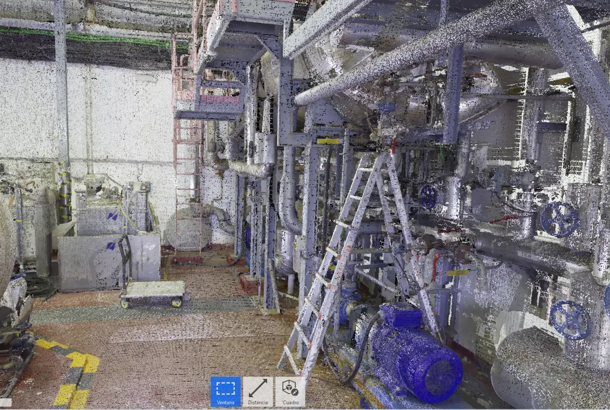
A vessel's engine room is possibly one of the most complex industrial spaces in existence: main engines, generators, compressors, pumps, electrical switchboards, ventilation ducts and hundreds of metres of piping, all concentrated in a confined space across multiple levels. 3D digitisation of engine rooms provides a complete model of the space with all components positioned with precision.
This documentation is especially valuable when planning the replacement of a main piece of equipment (an engine, a generator, an oily water separator) and it is necessary to verify that the new equipment fits in the available space, that piping connections match, and that extraction routes for maintenance are viable. Without a 3D model of the actual condition, this type of verification relies on partial measurements that do not always capture all geometric constraints.
Pipe routing documentation
Piping documentation is one of the applications where naval 3D scanning adds the most value. A typical vessel can have thousands of linear metres of piping for different services: fuel, cooling, fresh water, seawater, steam, hydraulic oil, bilges, fire-fighting, and many more. Documenting the actual routing of all these lines with manual measurements is weeks of work that still tends to contain errors.
Laser scanning captures the exact position of each pipe, including diameters, bends, support points and equipment connections. From the point cloud, our technicians model the pipe lines in Solid Edge and other CAD software, generating fabrication isometrics and installation drawings with actual dimensions. This process is the same one we apply in the digitisation of industrial land-based facilities, adapted to the particularities of the naval environment.
Retrofitting planning
Naval retrofitting —installing new equipment in existing vessels— is an increasingly frequent activity, driven by environmental regulations (ballast water treatment, emissions reduction, scrubbers), conversion to new fuels (LNG, methanol) and modernisation of propulsion and steering systems.
These projects share a common denominator: new equipment, often of considerable size, must be installed in spaces that were not designed to accommodate it. The key to success lies in planning, and planning depends on knowing the exact geometry of the available space. 3D scanning provides that information: a precise digital model of the vessel where the project team can design the installation, verify clashes, plan piping and cabling routes, and generate fabrication documentation, all before work starts at the shipyard.
The concept is the same as in any reverse engineering project: capturing the existing reality so that design tools can be used to work on it. The difference is scale: instead of a part of a few centimetres, we are dealing with complete sections of a vessel.
Documentation for classification societies
Classification societies (Lloyd’s Register, Bureau Veritas, DNV, among others) require exhaustive documentation of any structural or systems modification in a vessel. The 3D models generated from scanning provide a more complete and verifiable documentary base than traditional manual sketches and measurements. Furthermore, the point cloud constitutes a digital record of the vessel's condition at a specific moment, facilitating historical tracking and periodic inspections.
3D scanning equipment for the naval sector
Naval projects almost always require a combination of two types of scanning equipment, because the working scales are very different within the same project.
Trimble X7 for large spaces
The Trimble X7 terrestrial laser scanner is our equipment for large-volume capture. With a range of up to 80 metres and a capture speed of up to one million points per second, it can digitise complete hulls in dry dock, holds, decks and engine rooms in a reasonable time. Its auto-levelling and automatic registration system facilitates work in the not-always-ideal conditions of a shipyard: wet surfaces, vibrations, irregular lighting.
For each project, multiple scan stations are planned which, combined, cover the entirety of the space to be documented. The registration software automatically merges all scans into a single coherent point cloud, with a global accuracy of ±2 mm. This is the same technology we use in our 3D scanning of facilities service.
Creaform HandyScan MAX for specific components
When the project requires capturing detail geometries —a flange, a machinery part, a pipe support, a valve— we use the Creaform HandyScan MAX portable scanner, with an accuracy of ±0.15 mm and a resolution of 0.04 mm. This equipment allows individual components to be scanned with the precision needed to manufacture spare parts or verify assembly dimensions.
The combination of both devices covers the full range of scales in a naval project: from the overall view of the vessel to the detail of a specific part. It is the same philosophy we apply in our 3D scanning of parts service.
Advantages over traditional measurement methods
Until relatively recently, data capture in naval projects relied on manual measurements: tape measures, rulers, cardboard templates, thickness gauges and extensive hand sketching. Experienced technicians could obtain reasonable results, but the process had inherent limitations.
- Capture speed. A laser scanner captures millions of points in minutes. Documenting the same information manually can take days or weeks. In a context where drydocking time is money, the difference is significant.
- Information completeness. Manual measurements are, by nature, selective: the points the technician considers relevant are measured. 3D scanning captures everything, without prior selection criteria. If months after the scan the need arises to verify a dimension that was not initially measured, the information is in the point cloud.
- Elimination of cumulative errors. In manual measurements on large structures, errors accumulate. Each partial measurement introduces a small uncertainty that, added up over metres, can produce appreciable deviations. Laser scanning works with a global coordinate system that eliminates this accumulation.
- Objective and reusable documentation. A point cloud is an objective digital record of the vessel's condition. It does not depend on the interpretation of a sketch or a technician's handwriting. It can be measured, sectioned, compared and reused at any time, with any compatible software.
- Reduction of rework. With manual measurements, it is common for a workshop-fabricated part not to fit perfectly when it arrives at the vessel, because the actual dimensions differ slightly from those taken. With a precise 3D model of the space, parts are designed and fabricated with exact dimensions, drastically reducing on-site adjustments.
Workflow: from dry dock to CAD model
A typical naval 3D scanning project follows these phases:
If you want to learn more about indicative pricing for this type of project, we recommend our industrial 3D scanning pricing guide.
Case study: ballast water treatment system retrofitting
Case: BWTS Installation in an existing cargo vessel
Vessel: 95 m cargo ship, built in 2003 — Project: Installation of a ballast water treatment system (BWTS) for compliance with IMO D-2 regulations.
Situation: The shipowner needed to install a BWTS unit from a specific manufacturer in an available space adjacent to the engine room. The challenge was that no updated drawings existed for that area of the vessel: modifications made during more than 20 years of service were undocumented. It was necessary to verify that the equipment fitted in the available space, design the connecting pipe routes, and plan the work before the vessel entered dry dock to minimise drydocking time.
Process: Taking advantage of a port call, we scanned the planned installation area and adjacent spaces (engine room and accessible ballast tanks). The capture was completed in one working day with the Trimble X7 (14 stations) and the HandyScan MAX for existing flange connections. With the generated 3D model, the shipyard's project team was able to design the complete installation in CAD: equipment positioning, support structures, pipe routes, bulkhead penetrations and cable trays.
Result: When the vessel entered dry dock, the pre-fabricated pieces (piping, supports, equipment base) were ready with exact dimensions. The installation was completed in 12 days, compared to the 18–20 the shipyard estimated without prior 3D documentation. The saving of 6–8 drydocking days more than offset the cost of scanning.
Frequently asked questions
Can a complete vessel be scanned in dry dock?
Yes. Using our Trimble X7 laser scanner, we can capture the complete hull of a vessel in dry dock through multiple scan stations. The Trimble X7 has a range of up to 80 metres, allowing it to cover considerable lengths. For a vessel of 80–100 metres in length, the exterior hull scan can be completed in 1–2 working days. The resulting point cloud is automatically registered with an accuracy of ±2 mm, sufficient for repair planning, deformation verification and condition documentation.
What accuracy is achieved when scanning piping and naval components?
It depends on the equipment used. For general space scanning (engine rooms, holds, decks), the Trimble X7 offers an accuracy of ±2 mm, sufficient for pipe routing planning and general documentation. For specific components such as flanges, valves, supports or machinery parts, we use the Creaform HandyScan MAX with an accuracy of ±0.15 mm and resolution of 0.04 mm. The combination of both devices covers everything from the overall view of the space to the detail of each component.
How much does a naval 3D scanning project cost?
The cost depends on the scope of the project: scanning a section of an engine room is not the same as digitising a complete vessel. As a reference, an engine room scan with piping and main equipment modelling can range from 3,000 to 12,000 euros depending on complexity. For a specific quote, we need to know the type of vessel, the areas to scan and the required deliverables. You can consult our general guide on industrial 3D scanning prices for initial orientation.
Does 3D scanning meet the requirements of classification societies?
Yes. The main classification societies (Lloyd’s Register, Bureau Veritas, DNV, among others) accept 3D scanning-based documentation as support for condition inspections, hull thickness verification and modification documentation. The 3D models and drawings generated from scanning provide more complete and accurate documentation than traditional manual methods. Additionally, the point cloud remains as a digital record of the vessel's condition at a specific moment, which is very valuable for historical tracking.
Naval 3D scanning: let's talk about your project
If you need to digitise a vessel to plan a repair, document an engine room, design a retrofitting, or generate the documentation required by your classification society, we can help.
At PROMECAD we combine more than 20 years of experience in industrial mechanical design with state-of-the-art 3D scanning equipment. From Erandio (Bizkaia), we travel to shipyards and ports in the Basque Country, Cantabria, Asturias, Galicia and the entire Spanish coast. We work within the deadlines the naval sector demands and deliver directly applicable results: point clouds, CAD models, fabrication drawings and technical reports.
Tell us what you need. Write to us from our contact page or call us at 946 49 00 27. We will respond within 24 hours with an initial assessment.